Screwed stator frame for an electric motor and associated manufacturing process

A technology of a motor stator and a manufacturing method, which is applied in the manufacture of motor generators, stator/rotor bodies, and electric components, etc., can solve problems such as the formation of hot spots or magnetic imbalances, which are not conducive to the normal operation of motors.

Active Publication Date: 2018-01-30
ALSTOM TRANSPORT TECH SAS
View PDF10 Cites 0 Cited by
  • Summary
  • Abstract
  • Description
  • Claims
  • Application Information

AI Technical Summary

Problems solved by technology

These deformations may be transferred to the stator, which may impede the proper

Method used


Image

  • Screwed stator frame for an electric motor and associated manufacturing process
  • Screwed stator frame for an electric motor and associated manufacturing process
  • Screwed stator frame for an electric motor and associated manufacturing process

Examples


Embodiment Construction

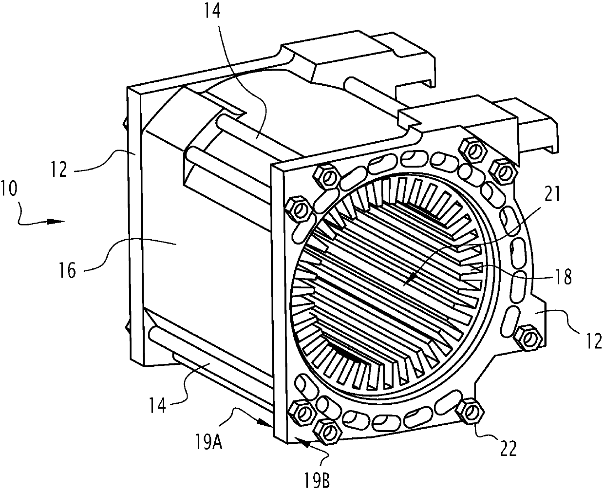
[0032] figure 1 The motor stator frame 10 shown in FIG. 2 includes two substantially parallel plates 12 and at least one bar 14 connecting the two plates 12 . Advantageously, the frame 10 comprises a side wall 16 fitted by clamping between two plates 12 and capable of housing and protecting the stator 18 of the electric motor.

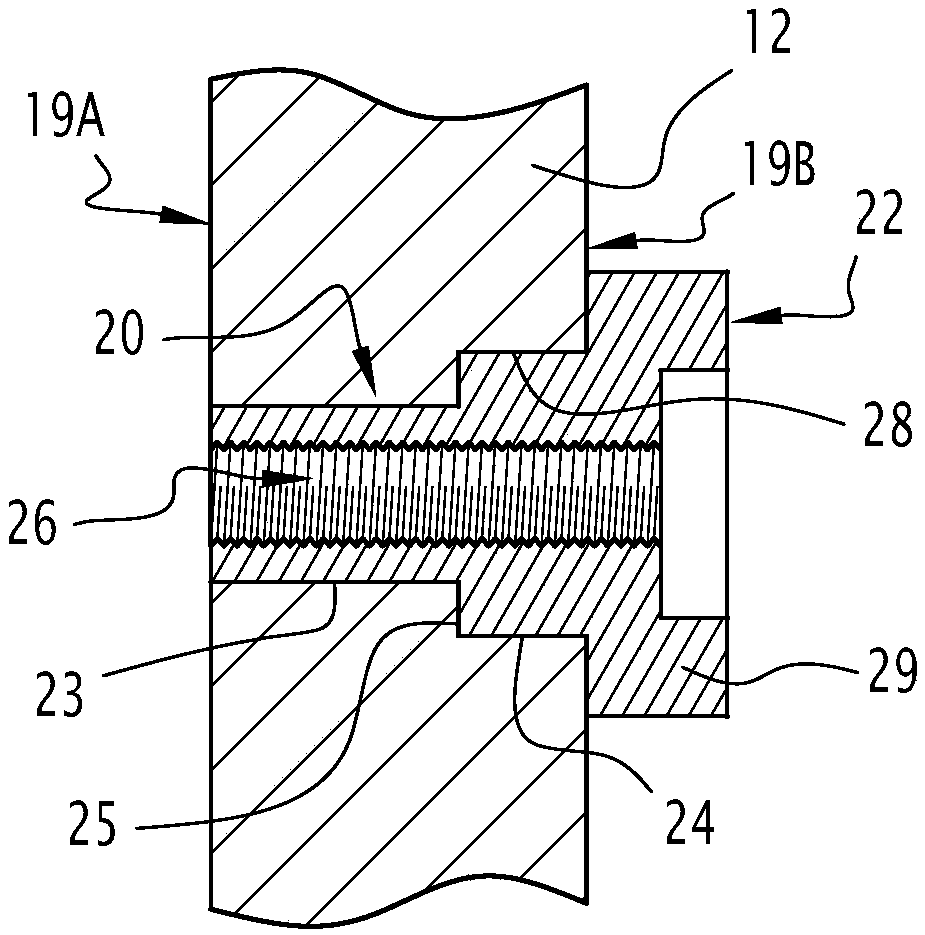
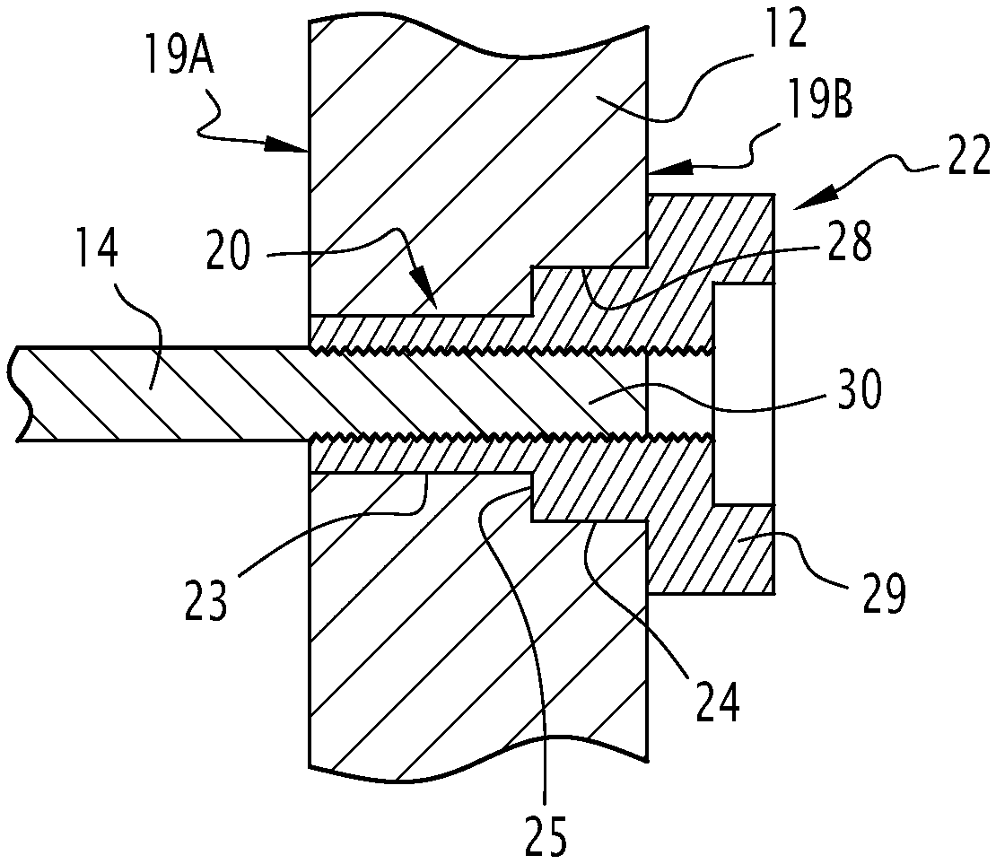
[0033] The plate 12 is molded from cast iron and is generally flat and has an inner face 19A and an outer face 19B. Both plates 12 also include at least one through hole 20 . By through hole is meant that each hole 20 is open at both ends thereof and opens onto the inner face 19A and the outer face 19B of the plate 12 . Each plate 12 also includes a generally circular central aperture 21 that allows passage of the rotor in the frame 10 .

[0034] Each hole 20 is punched in the plate 12 and has a circular cross-section. Additionally, each bore 20 receives a threaded bushing 22 . In addition, each hole 20 is composed of an inner section 23 opening o...


PUM


Abstract

A screwed stator frame for an electric motor and an associated manufacturing process are provided. A motor stator frame (10) including two plates (12) in cast iron; at least one steel bar (14) connecting both plates (12), each bar (14) having two threaded ends; and at least one threaded bushing (22). Wherein each of the plates (12) has at least one orifice being used as a seat for each threaded bushing (22) the threaded ends of each bar (14) being engaged into the threaded bushings (22).

Description

technical field [0001] The invention relates to a stator frame of an electrical machine comprising two plates of cast iron and at least one bar of steel connecting the two plates, each bar having two threaded ends. [0002] The stator frame serves to accommodate the rotor of an electric machine, in particular an electric machine involved in propelling a rail vehicle. Background technique [0003] A rail vehicle usually includes several electric machines of this type, which are positioned on the bogie and drive the wheels. For this purpose, the electric machine converts the electric power generated by the generator of the vehicle or provided directly by the supply cable into a rotary motion. [0004] These electric machines generally consist of a rotating part (rotor) and a stationary part (stator), which is attached in a frame which protects and insulates and houses the circuits used to cool the machine. [0005] The frame is a metal shell, usually of iron alloy, for examp...

Claims


Application Information

Patent Timeline
IPC IPC(8): H02K5/04
CPCH02K1/185H02K5/04H02K5/06H02K5/15H02K1/12H02K15/02H02K7/006H02K15/14
Inventor 布鲁诺·瑞金让-皮埃尔·隆巴尔盖坦·崔梅里
Owner ALSTOM TRANSPORT TECH SAS
Why Eureka
Try Eureka