Machining fine positioning pin positioning protection device

A protection device and machining technology, applied in the field of machining, can solve the problems of reduced precision positioning pin positioning accuracy, fine positioning pin damage, affecting the movement continuity of precision positioning pin positioning accuracy, etc., to avoid the influence of positioning accuracy, structure Simple, less bumpy effect

Active Publication Date: 2018-02-02
上海松森特殊金属有限公司
View PDF5 Cites 1 Cited by
  • Summary
  • Abstract
  • Description
  • Claims
  • Application Information

AI Technical Summary

Problems solved by technology

[0002] At present, in the machining process, when the product is finished, it is necessary to support and fix the product through the fine positioning pin, and then fix the product through the clamping cylinder opposite to the fine positioning pin, and then carry out the finishing process. During the process, the fine positioning pin is fixed, and then the product is installed on the fine positioning pin. During the installation process, the product will collide with the fine positioning pin, causing damage to the fine positioning pin and reducing the positioning accuracy of the fine positioning pin. It affects the processing accuracy of other dimensions. The existing protection of the fine positioning pin is to use the sleeve method, and the fine positioning pin is scaled in the sleeve. When positioning is required, the cylinder pushes the fine positioning pin to fix the product. After use , withdraw the fine positioning pin and protect it through the casing, but in the actual process, the processed metal chips are easy to fall into the casing, making the pulling and inserting action of the fine positioning pin stuck, affecting the continuity of the action and the fine positioning pin positioning accuracy

Method used


Image

  • Machining fine positioning pin positioning protection device
  • Machining fine positioning pin positioning protection device

Examples


Embodiment Construction

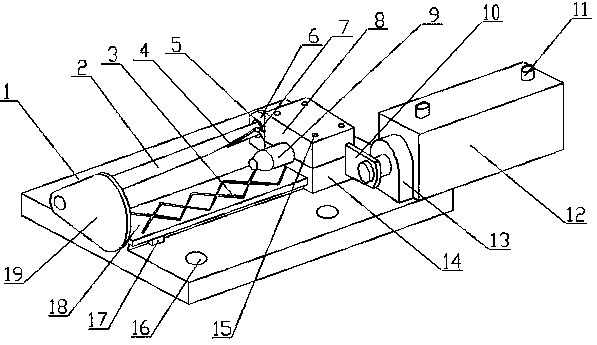
[0021] A machined fine positioning pin positioning protection device of the present invention is realized in this way. When in use, when finishing machining a machined product, first fix the base (1) in an appropriate position through the mounting hole (16), and then place the product Place the positioning pin on the other side of the protective plate (19), and connect the two connectors (11) on the cylinder (12) to the external air pipe respectively. When the product needs to be supported and fixed, the cylinder (12) will work. The telescopic rod on the cylinder (12) performs a stretching movement, and drives the sliding base (14) to move through the connecting plate (10), and the sliding base (14) moves to one end of the sliding rail (18) along the sliding rail (18), and the sliding base (14) Drive the fine positioning pin (9) to move to one end of the sliding rail (18) through the fixed cover plate (8), and the sliding base (14) drives the transmission lever (7) to move, and...


PUM


Abstract

The invention provides a machining fine positioning pin positioning protection device and discloses a device for driving a protection plate to eccentrically rotate through moving of a fine positioningpin, enabling the protection plate to be shielded between a product and the fine positioning pin, and protecting the fine positioning pin. The machining fine positioning pin positioning protection device is characterized in that multiple installing holes are formed in a base, a sliding rail is arranged on the base, the outer edge of one end of the sliding rail is flush with the outer edge of oneside of the base, two lubricating oil grooves are formed in the sliding rail and intersected to form a grid, a limiting block is arranged between one end of the sliding rail and the base, the slidingbase is arranged at the other end of the sliding rail in a sliding manner, a fixing cover plate is arranged on the sliding base and fixed through multiple fixing screws, the fine positioning pin is arranged on the fixing cover plate and located over the sliding rail, a supporting frame is arranged on the base and located on one side of the sliding base, one end of a transmission rod is arranged onthe supporting frame through a bearing, and the other end of the transmission rod extends along the sliding rail to be flush with one end of the sliding rail.

Description

technical field [0001] The invention relates to a positioning protection device for fine positioning pins in mechanical processing, which relates to a device for positioning and protecting fine positioning pins used in mechanical processing, and belongs to the field of mechanical processing. In particular, it relates to a device for protecting the fine positioning pin by driving the deflection of the protective plate through the movement of the fine positioning pin, so that the protective plate forms a shield between the product and the fine positioning pin. Background technique [0002] At present, in the machining process, when the product is finished, it is necessary to support and fix the product through the fine positioning pin, and then fix the product through the clamping cylinder opposite to the fine positioning pin, and then carry out the finishing process. During the process, the fine positioning pin is fixed, and then the product is installed on the fine positioni...

Claims


Application Information

Patent Timeline
Patent Type & Authority Applications(China)
IPC IPC(8): B23Q3/08B23Q11/00
CPCB23Q3/08B23Q11/00B23Q2703/04
Inventor 不公告发明人
Owner 上海松森特殊金属有限公司
Why Eureka
Try Eureka