Spindle speed reducing device

A deceleration device and spindle technology, applied in the direction of drive devices, metal processing machinery parts, metal processing equipment, etc., can solve the problems of poor deceleration effect, etc., and achieve good deceleration effect, convenient use, and good rotation

Inactive Publication Date: 2018-02-02
马少博
View PDF0 Cites 0 Cited by
  • Summary
  • Abstract
  • Description
  • Claims
  • Application Information

AI Technical Summary

Problems solved by technology

[0004] The purpose of the present invention is to provide a main shaft reduction device, which has the advantages of good deceleration effect and solves the problem of poor deceleration effect of the existing main shaft reduction device

Method used


Image

  • Spindle speed reducing device
  • Spindle speed reducing device

Examples


Embodiment Construction

[0016] The following will clearly and completely describe the technical solutions in the embodiments of the present invention with reference to the accompanying drawings in the embodiments of the present invention. Obviously, the described embodiments are only some, not all, embodiments of the present invention. Based on the embodiments of the present invention, all other embodiments obtained by persons of ordinary skill in the art without making creative efforts belong to the protection scope of the present invention.

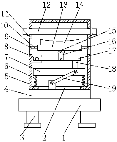
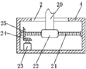
[0017] see Figure 1-2 , a spindle reduction device, including a worktable 1, the top of the workbench 1 is fixedly connected with a housing 4, the top of the housing 4 is fixedly connected with a protection box 5, and the tops of both sides of the inner wall of the protection box 5 are provided with chute 11 , by setting the chute 11, the sliding of the slider 9 on the inner wall of the protection box 5 is facilitated, the friction between the slider 9 and th...


PUM


Abstract

The invention discloses a main shaft reduction device, which comprises a workbench, the top of the workbench is fixedly connected with a casing, the top of the casing is fixedly connected with a protection box, and the tops of both sides of the inner wall of the protection box are provided with chute. The present invention is provided with a housing, a protection box, a spring, a support plate, a fixed block, a slider, a slide bar, a chute, a main shaft body, a first connecting plate, a deceleration pad, a fixing plate, a second connecting plate, and a third connecting plate , the first connecting rod, the second connecting rod, the third connecting rod, the threaded rod, the bushing, the motor, the first bevel gear and the second bevel gear can effectively decelerate the main shaft and achieve the deceleration The function with good effect solves the problem that most of the existing spindles are decelerated by gear meshing, so the deceleration effect is not good, which leads to the problem of low transmission accuracy, which is convenient for users to use and improves the processing speed of the spindle, suitable for popularization and use .

Description

technical field [0001] The invention relates to the technical field of spindles, in particular to a spindle reduction device. Background technique [0002] The main shaft refers to the shaft that receives power from the engine or motor and transmits it to other parts. The main shaft is also called "optical axis", which is the abbreviation of "main optical axis": a symmetrical diameter in the optical group, such as a spherical mirror The main axis of the main axis is a straight line passing through the center of the mirror surface and perpendicular to the mirror surface. The main axis of the lens or optical axis optical system is the connection line between the centers of each lens surface. An integrated new technology, together with linear motor technology and high-speed cutting tool technology, will push high-speed machining into a new era. The electric spindle is a set of components, which includes the electric spindle itself and its accessories: electric spindle, high-fre...

Claims


Application Information

Patent Timeline
Patent Type & Authority Applications(China)
IPC IPC(8): B23Q5/10
CPCB23Q5/10
Inventor 马少博
Owner 马少博
Why Eureka
Try Eureka