Container cargo handling movable bracket
A cargo loading and unloading, mobile technology, used in packaging, transportation and packaging, rigid containers, etc., can solve the problems of limited use scope, high investment cost, easy damage to the box floor, etc., to achieve safe and reliable use, high structural strength, and reduced The effect of loading and unloading investment costs
- Summary
- Abstract
- Description
- Claims
- Application Information
AI Technical Summary
Problems solved by technology
Method used
Image
Examples
Embodiment 1
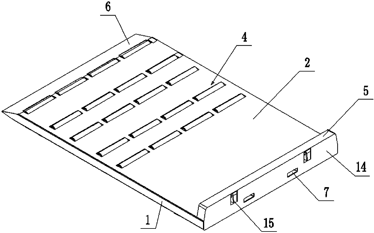
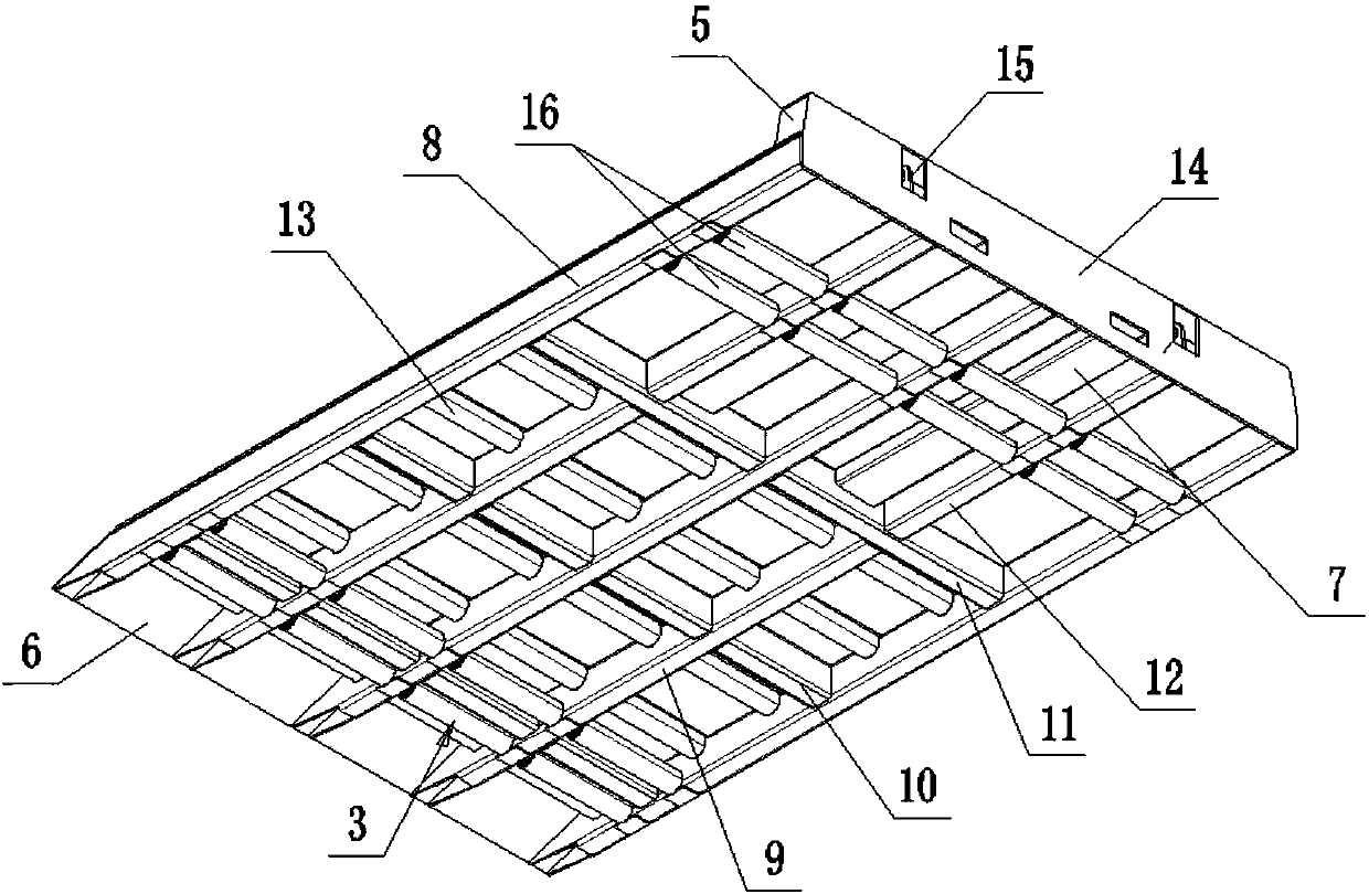
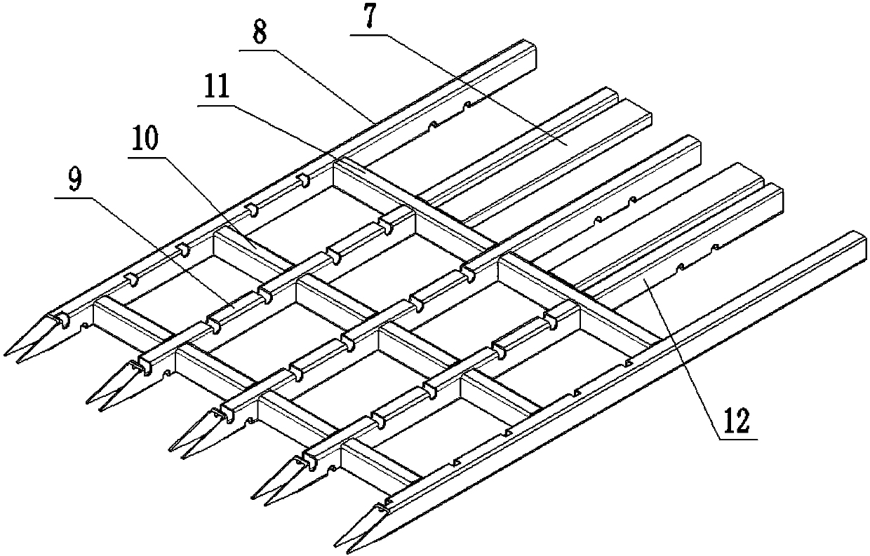
[0033] like Figures 1 to 3As shown, a container cargo loading and unloading mobile bracket includes a supporting frame 1, a panel 2, a moving roller 3, a guide roller 4, a push frame 5 and a shovel plate 6; the panel 2 is arranged on the upper side of the supporting frame 1, The moving roller 3 is hinged on the lower side of the supporting frame 1, the dredging roller 4 is hinged on the supporting frame 1 and partly penetrates above the panel 2, and the pushing frame 5 is arranged on the panel 1 and behind the supporting frame 1 end, the shovel plate 6 is located at the front end of the support frame 1 and is inclined downward, and a socket 7 is provided at the rear end of the support frame 1; the support frame 1 includes a support long rod 8, a first support short rod 9, a connecting Fixed rod 10, reinforced connecting rod 11 and second supporting short rod 12; described supporting long rod 8, the first supporting short rod 9, connecting fixed rod 10, strengthening connectin...
Embodiment 2
[0040] like Figures 4 to 10 As shown, on the basis of Embodiment 1, the bracket also includes a lift adjustment assembly, which includes a limit stop 17, an adjustment structure and a lift structure, and the limit stop 17 is arranged on the insertion sleeve 7 In the upper part of the inner side, the adjustment structure is arranged on the supporting frame 1 and the inserting sleeve 7, the lifting structure is arranged on the supporting frame 1, and the adjusting structure acts on the lifting structure; the adjusting structure includes a push plate 18, a top holding Block 19, push rod 20 and return spring 21, the push plate 18 is located in the reinforced connecting rod 11 and runs through the support rod 8, the holding block 19 is fixedly connected with the push plate 18 and one end penetrates into the insert sleeve 7, The push rod 20 is arranged in the support long rod 8 and the first support short rod 9 and one end is fixedly connected with the push plate 18, and the back-m...
PUM
 Abstract
Description
Claims
Application Information
 - R&D
- Intellectual Property
- Life Sciences
- Materials
- Tech Scout
- Unparalleled Data Quality
- Higher Quality Content
- 60% Fewer Hallucinations
Browse by: Latest US Patents, China's latest patents, Technical Efficacy Thesaurus, Application Domain, Technology Topic, Popular Technical Reports.
© 2025 PatSnap. All rights reserved.Legal|Privacy policy|Modern Slavery Act Transparency Statement|Sitemap|About US| Contact US: help@patsnap.com


