
Data output transmission mechanism

A technology of transmission mechanism and data, applied in the direction of transmission, transmission parts, gear transmission, etc., can solve the problems that the accuracy cannot meet the set requirements, and the backlash of gear meshing is not eliminated, so as to eliminate the backlash of gear meshing, Effects of reduced sensitivity requirements

Active Publication Date: 2018-02-02
GUIZHOU QUNJIAN PRECISION MACHINERY
View PDF10 Cites 1 Cited by
  • Summary
  • Abstract
  • Description
  • Claims
  • Application Information

AI Technical Summary

Problems solved by technology

[0003] In the prior art, when the launching device acquires the spatial rotation angle information of the azimuth mechanism through gear transmission, it adopts a deceleration transmission mode that does not eliminate the backlash of gear meshing. Reduce the rotation speed of the azimuth mechanism before outputting, so the data collector must have a higher sensitivity, otherwise, the accuracy of the spatial rotation angle information of the azimuth mechanism calculated through the data output by the gear transmission will not reach the set value Second, due to the existence of gear meshing backlash, when calculating the spatial rotation angle information of the azimuth mechanism through the data output by the gear transmission in the later stage, necessary technical processing must be performed on the impact caused by the gear meshing backlash, otherwise, all The obtained spatial rotation angle information of the azimuth mechanism is not the real data required

Method used


Image

  • Data output transmission mechanism
  • Data output transmission mechanism
  • Data output transmission mechanism

Examples


Embodiment Construction

[0020] In order to make the purpose, technical solution and advantages of the present invention clearer, the present invention will be further described in detail below in conjunction with the accompanying drawings and embodiments.

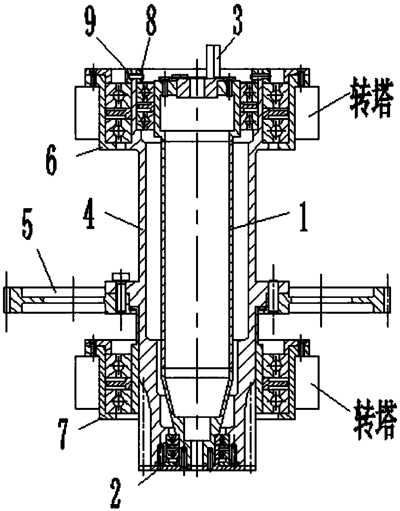
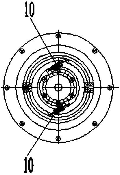
[0021] Embodiment of the present invention: the structural diagram of the data output transmission mechanism is as follows figure 1 and figure 2 As shown, it includes data output shaft 1, data output gear 2, data collector connection fork 3 and power input shaft 4. The data output shaft 1 and power input shaft 4 are thin-walled sleeve-shaped parts, and the power input The shaft 4 is set on the data output shaft 1, and the upper end and the lower end of the data output shaft 1 are respectively installed in the inner holes of the upper and lower ends of the power input shaft 4 through bearings; Cooperate with the power input shaft 4 through the hole shaft and then fix it axially through screws and positioning pins; the upper and lower ends of the ...


PUM


Abstract

The invention discloses a data output transmission mechanism. The data output transmission mechanism comprises a data output shaft, a data output gear, a data acquirer connection shifting fork and a power input shaft; the data output shaft and the power input shaft are each a thin-wall sleeve-shaped part; the data output shaft is sleeved with the power input shaft; the upper end and the lower endof the data output shaft are installed in inner holes of the upper end and the lower end of the power input shaft through bearings correspondingly; a power input gear is arranged on the middle portionof the power input shaft, and the power input gear and the power input shaft are fixedly connected in the axial direction through a screw and a positioning pin after being matched through a hole shaft; and the upper end and the lower end of the power input shaft are installed in inner holes of an upper supporting base and a lower supporting base correspondingly through bearings. According to thedata output transmission mechanism, when the space rotating angle information of an orientation mechanism is acquired by means of gear transmission, not only is a clearance eliminating gear structureadopted to eliminate the gear engaging side clearance, but also a speed increasing transmission manner is adopted for data output.

Description

technical field [0001] The invention relates to a data output transmission mechanism, which belongs to the technical field of gear transmission design. Background technique [0002] Gear transmission is widely used in launchers. The transmission device can change the transmission ratio between the power and the slewing mechanism by using the gear transmission, and can also use the gear transmission to stop the slewing mechanism with a large moment of inertia within the required braking angle range, and can also use the gear transmission to obtain the spatial rotation of the azimuth mechanism. angle information. [0003] In the prior art, when the launching device obtains the spatial rotation angle information of the azimuth mechanism through gear transmission, it adopts a deceleration transmission mode that does not eliminate the backlash of gear meshing. Its main shortcomings are manifested in two aspects: one is that the deceleration transmission is Reduce the rotation s...

Claims


Application Information

Patent Timeline
Patent Type & Authority Applications(China)
IPC IPC(8): F16H1/06F16H57/023G01C1/00
CPCF16H1/06F16H57/0025F16H57/023G01C1/00
Inventor 石年平
Owner GUIZHOU QUNJIAN PRECISION MACHINERY
Learn More