
Device capable of performing self-positioning multi-angle loading aging test on multiple torsional springs

An aging test and multi-angle technology, which is applied in the direction of measuring device, using stable torsion to test material strength, strength characteristics, etc., can solve the problems of not being able to meet small batch testing and complicated operation process, so as to save test cost and operate conveniently , the effect of simple structure

Pending Publication Date: 2018-02-02
SHANXI JIANGHUAI HEAVY IND
View PDF0 Cites 4 Cited by
  • Summary
  • Abstract
  • Description
  • Claims
  • Application Information

AI Technical Summary

Problems solved by technology

[0003] The invention provides a self-positioning multi-angle loading aging test device for multiple torsion springs, which solves the technical problems that the existing device cannot meet the requirements of small batch testing and the operation process is complicated

Method used


Image

  • Device capable of performing self-positioning multi-angle loading aging test on multiple torsional springs
  • Device capable of performing self-positioning multi-angle loading aging test on multiple torsional springs
  • Device capable of performing self-positioning multi-angle loading aging test on multiple torsional springs

Examples


Embodiment Construction

[0013] The present invention is described in detail below in conjunction with accompanying drawing:

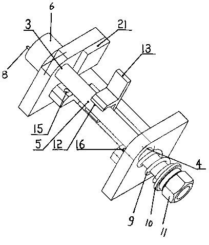
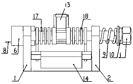
[0014] A self-positioning multi-angle loading aging test device for a plurality of torsion springs, including a left bracket baffle 1 and a right bracket baffle 2, and a connection between the left bracket baffle 1 and the right bracket baffle 2 Plate 14, on the left bracket baffle plate 1, be provided with pin shaft and pass through the left through hole 3, on the right bracket baffle plate 2, be provided with pin shaft through the right through hole 4, pass through the left through hole 3 and the pin shaft through the right A pin shaft rod 5 is movably inserted between the through holes 4, and a pin shaft head 6 is fixedly arranged on the left end of the pin shaft rod 5 passing out to the pin shaft through the left through hole 3, and a pin shaft head 6 is fixedly arranged on the left end of the pin shaft rod 5 passing through the left through hole 3, and a pin shaft head 6 i...


PUM


Abstract

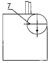
The invention discloses a device capable of performing a self-positioning multi-angle loading aging test on multiple torsional springs. The problem that an existing device cannot meet the requirementfor a small batch of testing is solved. Eccentric through holes (7) are formed in a hinge pin head (6), eccentric pin insertion holes (19) are arranged in the same circumference on the end face of theouter side of a left support baffle (1) at equal interval radian, eccentric pins (8) run through the eccentric through holes to be inserted into the eccentric pin insertion holes, a pin shaft rod (5)between the outer side face of a right support baffle (2) and a check ring (10) is sleeved with a compressed spring (9), an F-shaped switching plate (13) is clamped to an F-shaped switching plate clamping positioning table (12) through an end clamping opening in the F-shaped switching plate, a pin shaft rod between the left support baffle (1) and the F-shaped switching plate is sleeved with a torsional spring, the left end of the torsional spring is inserted into a torsional spring left end insertion hole (15), and the right end of the torsional spring is clamped to the F-shaped switching plate. The loading aging testing efficiency is improved, and the test cost is saved.

Description

technical field [0001] The invention relates to a loading aging test device for torsion springs, in particular to an efficient and simple testing device capable of carrying out loading aging tests on a plurality of torsion springs at the same time. Background technique [0002] The torsion spring is a torsion spring, and its two ends are fixedly connected to other components. When other components rotate around the center of the spring, the torsion spring pre-pulls it back to its initial position to generate torque or rotational force, which can be used to store the release angle. Energy or static fixation of certain devices by rotating the moment arm about the central axis of the spring body. After the torsion spring is manufactured, it needs to be subjected to a loading aging test to test whether its performance meets the requirements. The loading aging test is to place the torsion spring on a special tooling, twist it to a specified angle, test its torque value, and then...

Claims


Application Information

Patent Timeline
IPC IPC(8): G01N3/22G01N3/02
CPCG01N3/02G01N3/22G01N2203/0021
Inventor 张海林王玉兵李萌
Owner SHANXI JIANGHUAI HEAVY IND
Learn More