Structural damage real-time monitoring and positioning method

A technology for structural damage and real-time monitoring, applied in the testing field of real-time monitoring of structural temperature field, can solve the problems of limited resolution and complicated wiring in the central area, achieve good monitoring accuracy and accuracy, eliminate auxiliary equipment and wiring technology, Applicable to a wide range of effects

Inactive Publication Date: 2018-02-02
NANJING UNIV OF AERONAUTICS & ASTRONAUTICS
View PDF9 Cites 3 Cited by
  • Summary
  • Abstract
  • Description
  • Claims
  • Application Information

AI Technical Summary

Problems solved by technology

[0004] However, all the above works can only detect when damage occurs, which belongs to the first-level structural health monitoring (see Beomseok Kim, Yijiang Lu and Taemin Kim, et al.Carbon Nanotube Coated Paper Sensor for Damage Dia-gnosis[J].ACS NANO,2014 ,8(12):12092-12097.)
The second type of structural health monitoring technology detects where damage has occurred, which is a challenge for today's technology
Although the recently developed electrical impedance tomography (EIT) technique can localize damage (see T.N.Tallman, S.Gungor and K.W.Wang, et al. Tactileimaging and dist-ributed strain sensing in highly flexible carbon nanofiber / polyureth-ane nanocomposites[J] .Carbon,2015,95:485-493.), but this method requires many electrodes, complicated wiring, and limited resolution in the central region

Method used


Image

  • Structural damage real-time monitoring and positioning method
  • Structural damage real-time monitoring and positioning method
  • Structural damage real-time monitoring and positioning method

Examples


Embodiment Construction

[0027] The present invention will be further described below in conjunction with specific examples.

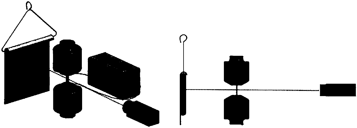
[0028] A method for real-time monitoring and positioning of structural damage, including the manufacture of a conductive film structural damage diagnostic sensor and a testing method for structural damage monitoring using it, specifically comprising the following steps:

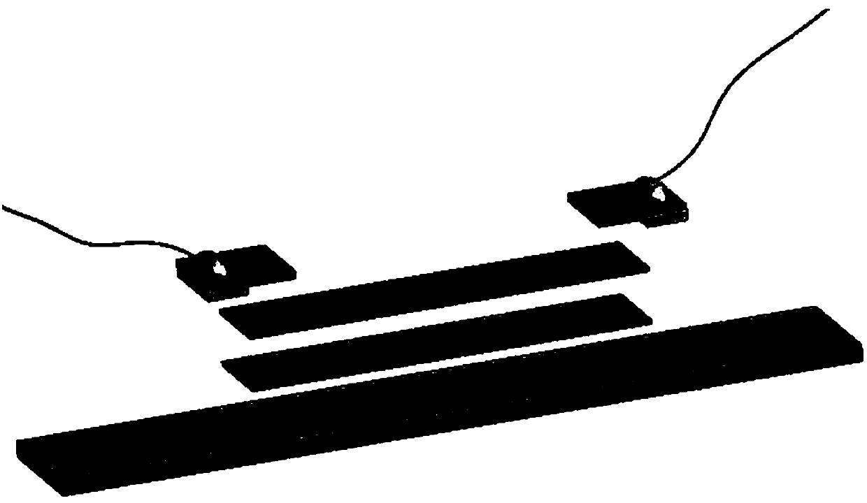
[0029] (1) Paste the carbon nanotube conductive film on the tensile test piece of the resin to be tested, and stick the electrode on the carbon nanotube conductive film, the sensor such as figure 1 shown;

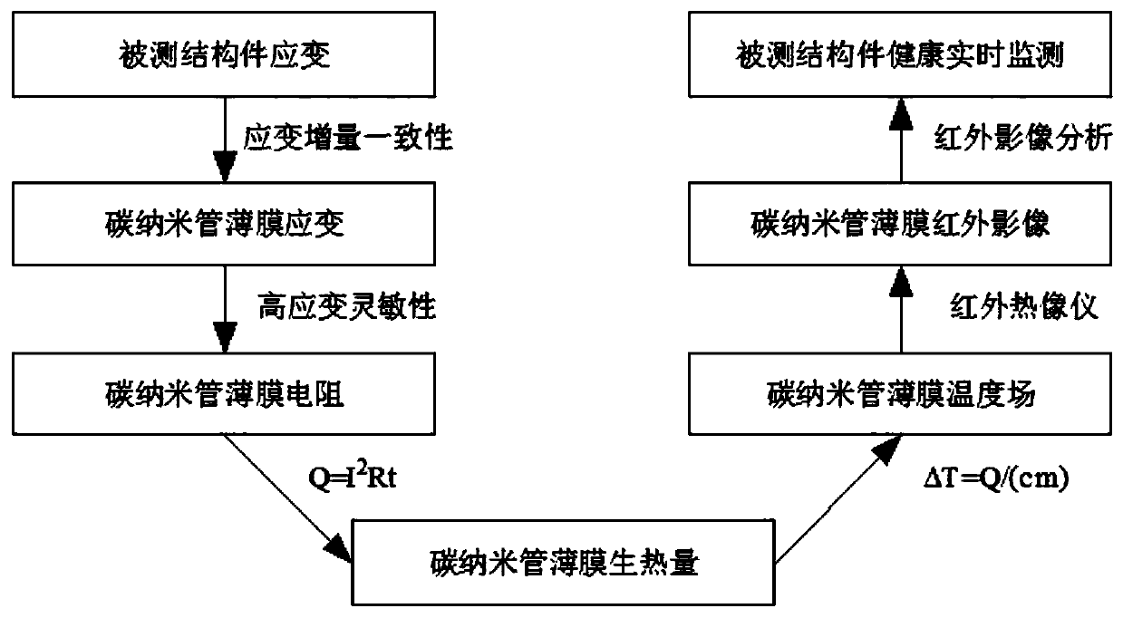
[0030] (2) The thickness of the carbon nanotube conductive film is less than 30 μm, ensuring that the self-strain energy of the conductive film is consistent with the strain of the measured structural member;

[0031] (3) The strain sensitivity factor of the conductive film is 6.79, which can reflect the strain change of itself in the form of resistance change;

[0032] (4) Apply electricity to the condu...


PUM

PropertyMeasurementUnit
thicknessaaaaaaaaaa

Abstract

The invention relates to a structural damage real-time monitoring and positioning method which includes manufacture of a conductive film structural damage diagnosis sensor and a testing method for monitoring structural damage by the sensor. A conductive film is laminated on a tested structural part, an electrode is laminated on the conductive film, the conductive film is powered on, a film temperature field is monitored by an infrared thermal imager, stress is higher in an area with higher temperature, a temperature concentration area is an area with the damage, and the structural damage is monitored and positioned. Structural damage real-time monitoring and positioning are realized, materials for manufacture are conveniently and easily obtained and low in cost, the manufacture process iseasy to understand and flexible in operation, and structural damage positions and damage degrees are remotely, accurately and effectively detected and diagnosed in real time.

Description

technical field [0001] The invention relates to the technical field of non-destructive testing, in particular to a testing method for real-time monitoring of the structural temperature field using a carbon nanotube film as a structural damage diagnosis sensor combined with an infrared thermal imager. Background technique [0002] A major task in structural design is to avoid damage to the structure during its operation. However, due to numerous unpredictable external factors such as: external loads, working environment, manufacturing process, etc., it is difficult to know exactly when and how structural damage occurs. For these reasons, structural health monitoring has been paid attention to by many fields such as civil aviation, automobile industry and high-pressure vessels (see Beomseok Kim, Yijiang Lu and Taemin Kim, et al.Carbon Nanotube Coated Paper Sensor for Damage Diagnosis[J].A- CS NANO, 2014, 8(12): 12092-12097.). Traditional sensors such as strain gauges and pie...

Claims


Application Information

Patent Timeline
Patent Type & Authority Applications(China)
IPC IPC(8): G01N25/72
CPCG01N25/72
Inventor 高希光王赛宋迎东
Owner NANJING UNIV OF AERONAUTICS & ASTRONAUTICS
Why Eureka
Try Eureka