Supercharge Your Innovation With Domain-Expert AI Agents!

Workbench and Exposure Device

A workbench and workpiece technology, which is applied in the exposure device of photolithography process, microlithography exposure equipment, optics, etc., can solve the problems of workpiece deformation and vacuum adsorption, and achieve simple structure, low cost, easy operation and positioning Effect

Active Publication Date: 2021-03-26
USHIO DENKI KK
View PDF6 Cites 0 Cited by
  • Summary
  • Abstract
  • Description
  • Claims
  • Application Information

AI Technical Summary

Problems solved by technology

[0009] In a workbench equipped with such a vacuum suction mechanism, there is a problem that sufficient vacuum suction cannot be performed due to deformation of the workpiece.

Method used


Image

  • Workbench and Exposure Device
  • Workbench and Exposure Device
  • Workbench and Exposure Device

Examples


Embodiment Construction

[0058] Next, modes for carrying out the invention of the present application (hereinafter referred to as embodiments) will be described.

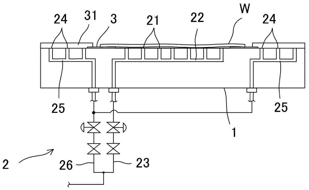
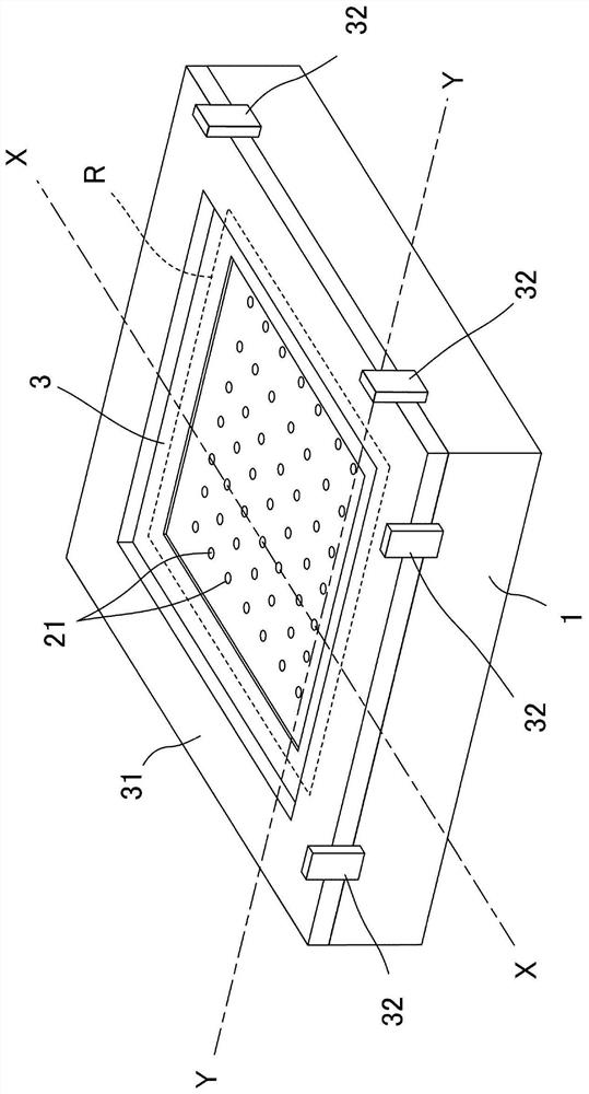
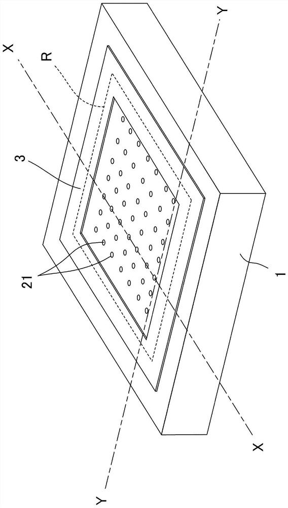
[0059] figure 1 It is a schematic front cross-sectional view of the workbench of the embodiment, figure 2 for figure 1 A schematic perspective view of the workbench shown, image 3 for figure 1 A schematic perspective view of the main parts of the workbench shown.

[0060] Figure 1 ~ Figure 3 The table of the illustrated embodiment holds a plate-shaped workpiece W and includes a table main body 1 . The table main body 1 is a rectangular table-shaped member in plan view. In this embodiment, the table main body 1 holds the workpiece|work W in a horizontal posture, and the upper surface which is a horizontal flat surface becomes a workpiece|work holding surface.

[0061] Such as Figure 1 ~ Figure 3 As shown, the table main body 1 has a plurality of vacuum suction holes 21 for workpieces. On the upper surface of the table main body ...


PUM

PropertyMeasurementUnit
thicknessaaaaaaaaaa

Abstract

To provide an inexpensive table that can sufficiently absorb and hold deformed workpieces without causing damage to the workpieces, and that is easy to handle even workpieces of different sizes. The shrink piece (3) provided on the workpiece holding surface of the table main body (1) on which the plate-shaped workpiece W is placed is in the shape of a frame surrounding the area where the workpiece vacuum suction hole (21) is provided. When the workpiece W) is placed on the workpiece holding surface and sucked by vacuum suction through the workpiece vacuum suction hole (21), the contraction sheet (3) is sandwiched between the workpiece W and the table main body (1). The shrinkable piece (3) has a shape extending along the peripheral portion of the workpiece (W), and shrinks in the thickness direction due to elasticity in response to deformation of the workpiece (3), so as to be in close contact with the workpiece (W).

Description

technical field [0001] The invention of the present application relates to a stage for holding a workpiece to be processed at a predetermined position, and also relates to an exposure apparatus equipped with such a stage. Background technique [0002] In an apparatus that performs various treatments, it is often necessary to hold an object to be treated (hereinafter, referred to as a workpiece) at a predetermined position. At this time, when the workpiece is plate-shaped, it is often placed and held on a table-shaped member (hereinafter, referred to as a table) having a flat surface, and such a table is called a table. [0003] In order to securely hold the workpiece, the table is often provided with a mechanism for sucking the workpiece, and among these mechanisms, a vacuum suction mechanism for sucking the workpiece by vacuum is often used. A vacuum suction hole is formed on the workpiece holding surface of the table, and a vacuum exhaust path communicating with the vacuu...

Claims


Application Information

Patent Timeline
Patent Type & Authority Patents(China)
IPC IPC(8): G03F7/20
CPCG03F7/20G03F7/70716G03F7/70708G03F7/70833
Inventor 原贵之
Owner USHIO DENKI KK
Features
  • R&D
  • Intellectual Property
  • Life Sciences
  • Materials
  • Tech Scout
  • Unparalleled Data Quality
  • Higher Quality Content
  • 60% Fewer Hallucinations
Learn More