System state display method and device based on CPLD (Complex Programmable Logic Device)

A system status and display method technology, applied in the direction of instruments, electrical digital data processing, hardware monitoring, etc., can solve the problem that BMC cannot monitor and control the system in real time, and achieve the effect of stable and comprehensive collection of CPLD

Active Publication Date: 2018-02-02
SUZHOU LANGCHAO INTELLIGENT TECH CO LTD
View PDF5 Cites 15 Cited by
  • Summary
  • Abstract
  • Description
  • Claims
  • Application Information

AI Technical Summary

Problems solved by technology

[0005] The purpose of the present invention is to provide a CPLD-based system status display method and device, aiming to solve the problem that the BMC in the server system cannot monitor and control the entire system in real time throughout the whole process, and realize system monitoring and control using CPLD to assist BMC

Method used


Image

  • System state display method and device based on CPLD (Complex Programmable Logic Device)
  • System state display method and device based on CPLD (Complex Programmable Logic Device)

Examples


Embodiment Construction

[0023] In order to clearly illustrate the technical features of the present solution, the present invention will be described in detail below through specific implementation methods and in conjunction with the accompanying drawings. The following disclosure provides many different embodiments or examples for implementing different structures of the present invention. To simplify the disclosure of the present invention, components and arrangements of specific examples are described below. Furthermore, the present invention may repeat reference numerals and / or letters in different instances. This repetition is for the purpose of simplicity and clarity and does not in itself indicate a relationship between the various embodiments and / or arrangements discussed. It should be noted that components illustrated in the figures are not necessarily drawn to scale. Descriptions of well-known components and processing techniques and processes are omitted herein to avoid unnecessarily lim...


PUM


Abstract

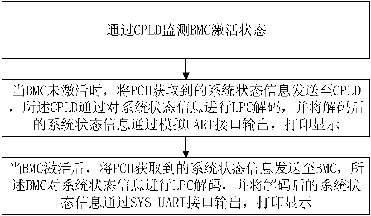
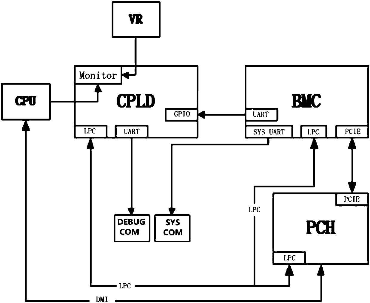
The invention provides a system state display method and device based on a CPLD (Complex Programmable Logic Device). The method comprises the following steps that: through the CPLD, monitoring the activation state of a BMC (Baseboard Management Controller); when the BMC is not activated, sending system state information obtained by a PCH (Platform Controller Hub) to the CPLD, carrying out LPC (Linear Predictive Coding) decoding on the system state information by the CPLD, outputting the decoded system state information through a simulation UART (Universal Asynchronous Receiver/Transmitter) interface, and displaying the decoded system state information; when the BMC is activated, sending the system state information obtained by the PCH to the BMC, carrying out LPC decoding on the system state information, and outputting and displaying the decoded system state information through an SYS UART interface. By use of the method, a CPLD chip is selected to assist the BMC in outputting the system UART interface, a GPIO (General Purpose Input/Output), the LPC and the UART is analyzed, the relevant signal of a peripheral chip is detected, the UART interface output is simulated, and therefore,state information can be more comprehensively collected.

Description

technical field [0001] The invention relates to the technical field of computer servers, in particular to a CPLD-based system status display method and device. Background technique [0002] With the development of information technology, servers are used more and more widely, and the performance of servers is also continuously upgraded. BMC (Baseboard Management Controller, Baseboard Management Controller) is the main control chip and monitoring chip in the server system. There are more and more jobs, and more and more information needs to be collected and monitored. [0003] Due to the limited number of logic units and pins of the BMC, it is impossible to capture fast-changing system signals, and because the BMC itself needs a certain startup time and restart operation restrictions, the entire system cannot be monitored in real time at a certain point in time and control; and BMC has many monitoring and management functions for the system, and the load is relatively large,...

Claims


Application Information

Patent Timeline
Patent Type & Authority Applications(China)
IPC IPC(8): G06F11/32
CPCG06F11/328
Inventor 奚立达宋丽青
Owner SUZHOU LANGCHAO INTELLIGENT TECH CO LTD
Why Eureka
Try Eureka