
Visualized analysis method for energy distribution under disk structure collision impact

A technology of energy distribution and analysis method, which is applied in the field of data processing, can solve the problems of no vibration energy, large calculation amount and difficulty, stress and displacement can not provide vibration characteristics, etc., and achieve the effect of small calculation amount and high calculation accuracy

Active Publication Date: 2018-02-02
青岛绿色发展研究院有限公司
View PDF3 Cites 0 Cited by
  • Summary
  • Abstract
  • Description
  • Claims
  • Application Information

AI Technical Summary

Problems solved by technology

The disadvantage is that the traditional displacement and stress are still used as the conditions for judging the strength of vibration, and there is no concept of vibration energy.
The disadvantage of this method is still the lack of analysis from the perspective of energy, and the simple stress and displacement cannot provide all the information of the vibration characteristics.
Another scholar provides an analytical method, which is characterized by analyzing the transient response through the dynamic equation of the rotor, but the disadvantage is that the method has large limitations and a large amount of calculation is difficult to solve

Method used


Image

  • Visualized analysis method for energy distribution under disk structure collision impact
  • Visualized analysis method for energy distribution under disk structure collision impact
  • Visualized analysis method for energy distribution under disk structure collision impact

Examples


Embodiment 1

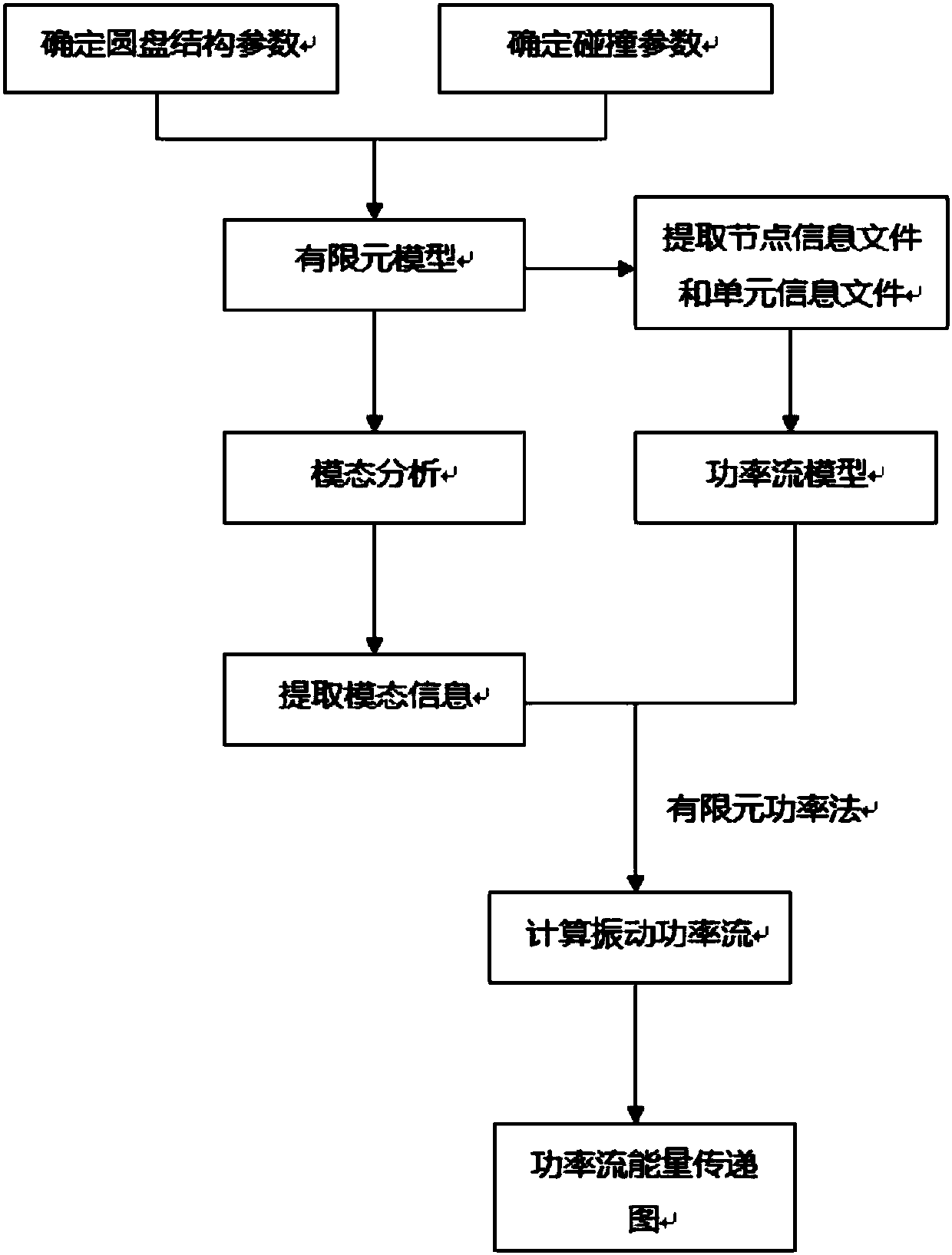
[0041] In this embodiment, the energy distribution visualization flow chart under the collision of the disc structure is as follows: figure 1 shown.

[0042] (1) Determine the model parameters of the two disk structures during the collision process. The model parameters of the collided body mainly include: a diameter of 150mm, a density of 7800kg / m3, a Young's modulus of 206Gpa and a Poisson's ratio of 0.3. The collision body model parameters mainly include a diameter of 10mm, a density of 7800kg / m3, a Young's modulus of 206Gpa and a Poisson's ratio of 0.3.

[0043] (2) Determine the collision parameters of the disc structure: the initial velocity is 1000m / s.

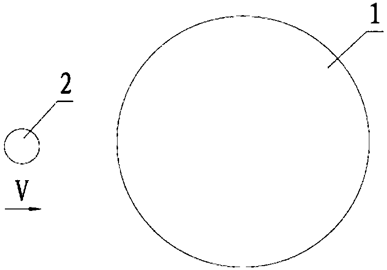
[0044] (3) According to the above parameters, a finite element model is established, the collided disk 1 has no freedom constraints, and the colliding body 2 with initial velocity V is treated as a rigid body. Transient response analysis is carried out to obtain the modal information of the collided disc, which mainl...


PUM


Abstract

The invention discloses a visualized analysis method for energy distribution under a disk structure collision impact. The method comprises the following steps that: a: determining the model parameterof a collided disk structure; b: determining the collision parameter of the disk structure; c: establishing a finite element model, and carrying out transient state response to obtain the modal information of the collided disk structure; d: extracting the node information file and the unit information file of the collided disk structure, generating a power flow model, and calculating vibration power; and e: obtaining a power flow power flow and an energy wave cloud picture, comparing with a stress wave cloud picture to obtain an energy transfer path and an energy distribution change situationof the disk structure under collision. By use of the method, a finite element power flow method is used for carrying out visualized analysis on the energy distribution and transmission path of the disk structure under collision, all information of vibration characteristics can be provided, a calculated amount is small, calculation accuracy is high, and the size and the direction of the energy transferring of the disk structure at any moment can be quickly and accurately obtained.

Description

technical field [0001] The invention relates to a visual analysis method for energy distribution of a disk structure under collision impact, which can quickly and accurately observe the energy distribution and transmission of the disk structure under collision impact, and belongs to the technical field of data processing. Background technique [0002] With the rapid development of science and technology, various equipment in industries such as machinery, aviation, spaceflight, shipbuilding and construction are developing towards multifunctional and complex directions. The power conversion frequency is also extended from the original low frequency area to the high frequency area. The precision requirements and reliability requirements of industrial processing are getting higher and higher. At the same time, the power required for production and processing is also gradually increasing, and the vibration energy is gradually increasing, which leads to increasingly prominent stru...

Claims


Application Information

Patent Timeline
IPC IPC(8): G06F17/50
CPCG06F30/17G06F30/23G06F2119/06Y02E60/00
Inventor 向玲郭曦煜胡爱军周晨光郭鹏飞高楠邓泽奇
Owner 青岛绿色发展研究院有限公司
Learn More