Low voltage reactive power compensation calculation method based on improved particle swarm algorithm

A particle swarm algorithm and calculation method technology, applied in reactive power compensation, reactive power adjustment/elimination/compensation, AC network circuits, etc., can solve problems such as low power factor and ineffective power equipment

Active Publication Date: 2018-02-02
SHANGHAI INST OF TECH
View PDF1 Cites 6 Cited by
  • Summary
  • Abstract
  • Description
  • Claims
  • Application Information

AI Technical Summary

Problems solved by technology

[0003] The present invention aims at the above-mentioned technical problem that the power factor is low and the power equipment cannot effectively play its role, and proposes a low-voltage reactive power compensation calculation method based on an improved particle swarm algorithm

Method used


Image

  • Low voltage reactive power compensation calculation method based on improved particle swarm algorithm
  • Low voltage reactive power compensation calculation method based on improved particle swarm algorithm
  • Low voltage reactive power compensation calculation method based on improved particle swarm algorithm

Examples


Embodiment Construction

[0053] The technical solutions proposed by the present invention will be further described in detail below in conjunction with the accompanying drawings and specific embodiments. Advantages and features of the present invention will be apparent from the following description and claims. It should be noted that all the drawings are in very simplified form and use imprecise ratios, which are only used for the purpose of conveniently and clearly assisting in describing the embodiments of the present invention.

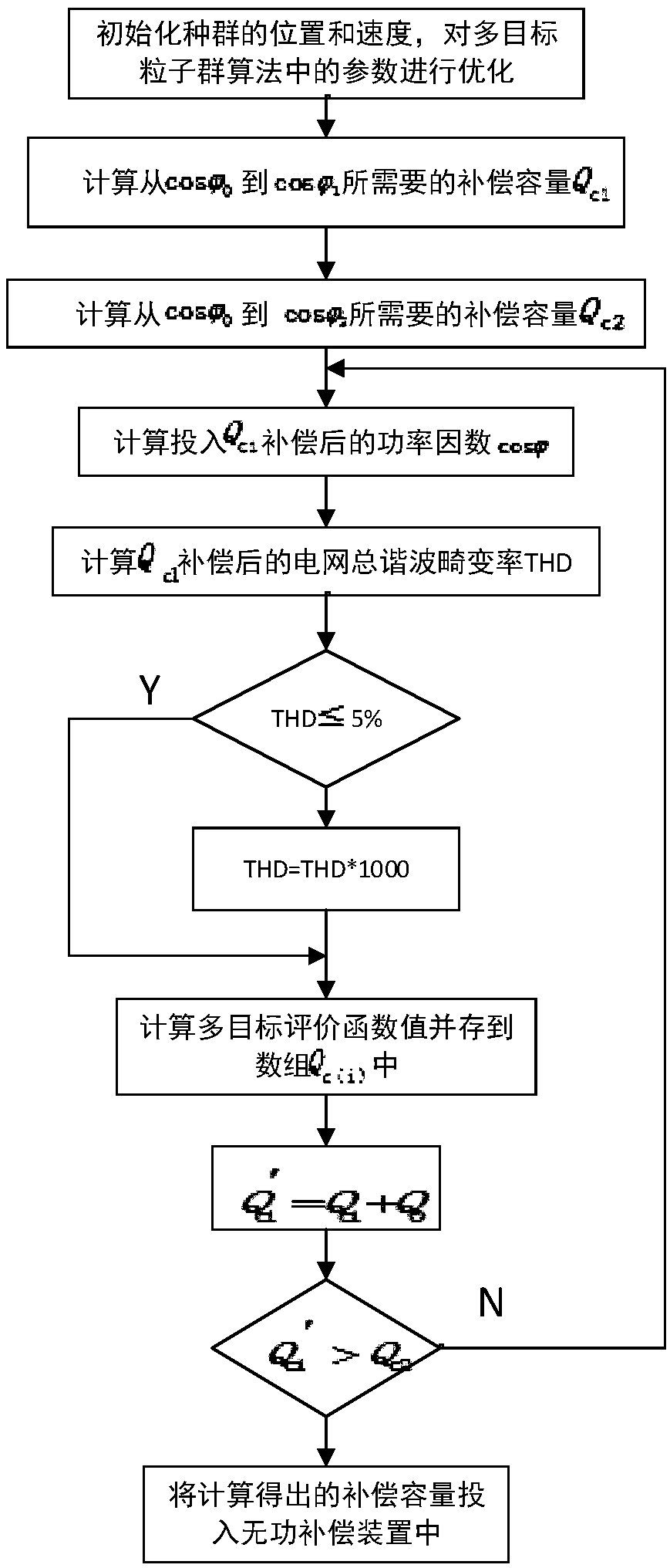
[0054]The low-voltage reactive power compensation calculation method based on the improved particle swarm optimization algorithm of the present invention is mainly based on the optimization of parameters such as inertia weight ω and learning factor c in the multi-objective particle swarm optimization algorithm, and the power factor and the voltage distortion rate THD as the objective function to find the optimized compensation capacity Q c , the calculated compensation ...


PUM


Abstract

The present invention relates to the technical field of reactive power compensation and particularly relates to a low voltage reactive power compensation calculation method based on improved particleswarm algorithm. Based on the optimization of parameters of an inertia weight omega and a learning factor c in a multi-objective particle swarm optimization, a power factor COS phi and a voltage distortion ratio THD are used as objective functions, an optimized compensation capacity Qc is calculated, and then the calculated compensation capacity Qc is inputted into a reactive power compensation device. The amplification of harmonic waves by the reactive power compensation can be reduced, the influence on grid parameters is reduced, and thus the effect of reactive power compensation is improved.

Description

technical field [0001] The invention relates to the technical field of reactive power compensation, in particular to a low-voltage reactive power compensation calculation method based on an improved particle swarm algorithm. Background technique [0002] Like active power, reactive power is an integral part of ensuring power quality and power system operation. Since the reactive power will increase the current in the line during the transmission process of the line, which will increase the loss of equipment and lines, resulting in a large loss of active energy. At the same time, the power factor is low, making the terminal voltage of the load drop, and even If the voltage at the user end does not reach the specified value, the power equipment will not be able to fully play its role, resulting in a great waste of energy. The power grids built in my country, especially the vast rural power grids, generally have low power factors and large power grid losses. The main reason fo...

Claims


Application Information

Patent Timeline
Patent Type & Authority Applications(China)
IPC IPC(8): H02J3/18
CPCH02J3/18H02J2203/20Y02E40/30
Inventor 徐兵房超
Owner SHANGHAI INST OF TECH
Why Eureka
Try Eureka