Collimating lens and automotive optical module

A technology of collimating lens and optical module, which is applied in the optical system field of matrix headlights, can solve the problems of cost increase and achieve the effect of unit cost reduction, increased strength and rigidity, and low processing difficulty

Pending Publication Date: 2018-02-06
HASCO VISION TECHNOLOGY CO LTD
View PDF4 Cites 9 Cited by
  • Summary
  • Abstract
  • Description
  • Claims
  • Application Information

AI Technical Summary

Problems solved by technology

This also increases the cost

Method used


Image

  • Collimating lens and automotive optical module
  • Collimating lens and automotive optical module
  • Collimating lens and automotive optical module

Examples


Embodiment Construction

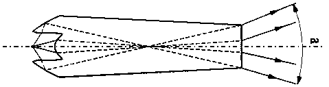
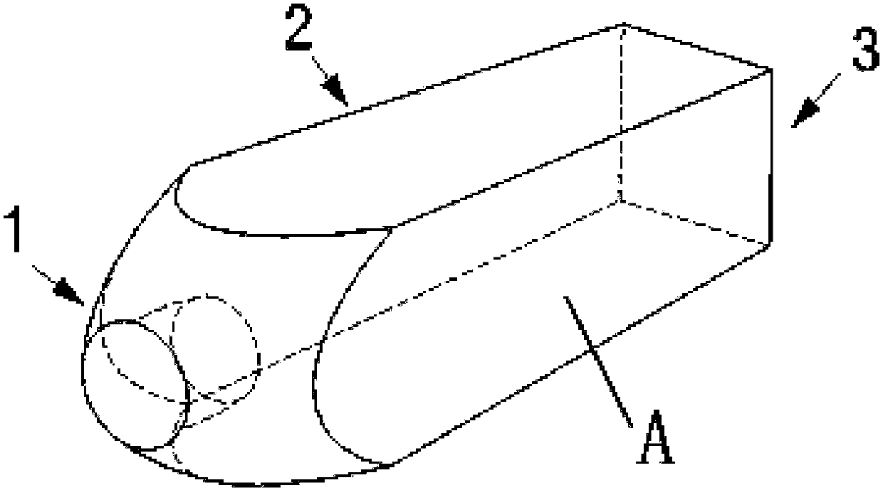
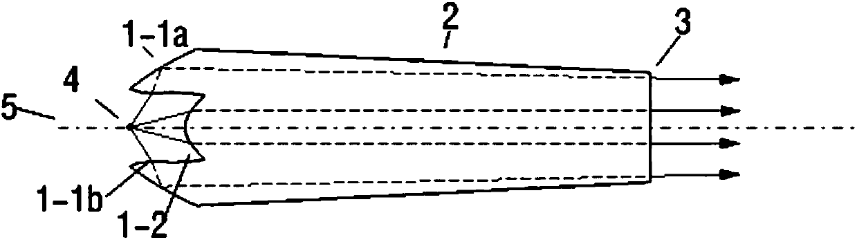
[0060] Such as figure 1 As shown, the present invention discloses a collimator lens, which is in the shape of a cone. The light-focusing end is a special-shaped structure that protrudes backward as a whole, is concave at the center, and the bottom surface of the depression protrudes backward. On the light emitting surface, the radially outermost surface 1-1a of the light concentrating end is a total reflection surface. The light-focusing end has a focal point, which is located on the optical axis 5, behind the bottom surface of the depression, and in an area close to the rear edge of the light-condensing end. The light emitted from the focal point can pass through the light-condensing end and exit the light-emitting surface parallelly and directly, or form a cross and exit the light-emitting surface at a certain angle. The focal point 4 is preferably a light source placement point. The surface other than the light-emitting surface and the light-concentrating end surface is ...


PUM


Abstract

A collimating lens and an automotive optical module are disclosed. The collimating lens is cone-shaped, the front end surface of the collimating lens is a light-emitting surface and the rear end of the collimating lens is a light-condensing end. The light-condensing end is protruded backward as a whole and has a recess in the center, the bottom surface of the recess is protruded backward, and theradially outermost surface of the light-condensing end is a side wall. The light-condensing end has a focal point located in a region behind the bottom surface of the recess and near the edge of the rear end of the light-condensing end. The surface, other than the light-emitting surface and the light-condensing end surface, is the side wall, and the side wall is a plane or a curved surface continuous in the forward and backward direction. The automotive optical module comprises one or more groups of collimating lens units. Each collimating lens unit comprises an LED light source and the collimating lens, wherein the LED light source and the collimating lens are corresponding to each other, and the light source is arranged at the focal point of the collimating lens. The collimating lens units are arranged in a matrix and in one row or more rows at intervals, and the side walls on the sides of the light sources at the intervals are connected with ribs. The two modules are cooperated together during use to form a continuous light type. The collimating lens and the automotive optical module have high light utilization efficiency and simple process of molds, and are suitable for matrixtype headlights.

Description

technical field [0001] The invention relates to a collimating lens and a vehicle optical module using the lens. The collimating lens and the vehicle optical module using the lens have higher optical efficiency and can be used in the optical system of matrix headlights . Background technique [0002] In recent years, car lighting technology is changing with each passing day, and matrix headlights will be a trend in the next few years. Matrix headlights are a combination of multiple light sources. Through the radar and sensors in the car, various driving conditions are collected, and then the intelligent system is used to control the sub-light sources, so that the light pattern can automatically adapt to the driving environment. Due to the technical difficulty of matrix headlights, they were initially only used in a few high-end models, such as Mercedes-Benz and Audi. With the promotion of marketization, more and more mid-level models are equipped with matrix headlights. Th...

Claims


Application Information

Patent Timeline
Patent Type & Authority Applications(China)
IPC IPC(8): F21V5/04F21S41/141F21S41/25F21W107/10F21W102/13F21Y115/10
CPCF21V5/007F21V5/04F21Y2115/10F21S41/143F21S41/151
Inventor 张大攀仇智平
Owner HASCO VISION TECHNOLOGY CO LTD
Why Eureka
Try Eureka