
Aero-engine blisk annular cutter machining method based on control line

A technology of aero-engines and integral blisks, applied in the direction of manufacturing tools, metal processing equipment, milling machine equipment, etc., can solve the problems of low processing quality, complicated operation process, low efficiency, etc., to improve the processing surface quality, high efficiency, The effect of reducing man-hours

Active Publication Date: 2018-02-06
NORTHWESTERN POLYTECHNICAL UNIV
View PDF6 Cites 15 Cited by
  • Summary
  • Abstract
  • Description
  • Claims
  • Application Information

AI Technical Summary

Problems solved by technology

[0006] In order to overcome the disadvantages of complex operation process, low processing quality and low efficiency in the prior art, the present invention proposes a method for machining the blisk of an aero-engine with a circular knife based on the control line, and uses the control line to calculate the cutting of the blisk with the circular knife The tool position point and tool axis vector of the blade, plan the milling tool trajectory of the blisk, and apply it to the processing of the whole blisk

Method used


Image

  • Aero-engine blisk annular cutter machining method based on control line
  • Aero-engine blisk annular cutter machining method based on control line
  • Aero-engine blisk annular cutter machining method based on control line

Examples


Embodiment Construction

[0033] The present invention will be further described below in conjunction with the accompanying drawings and embodiments.

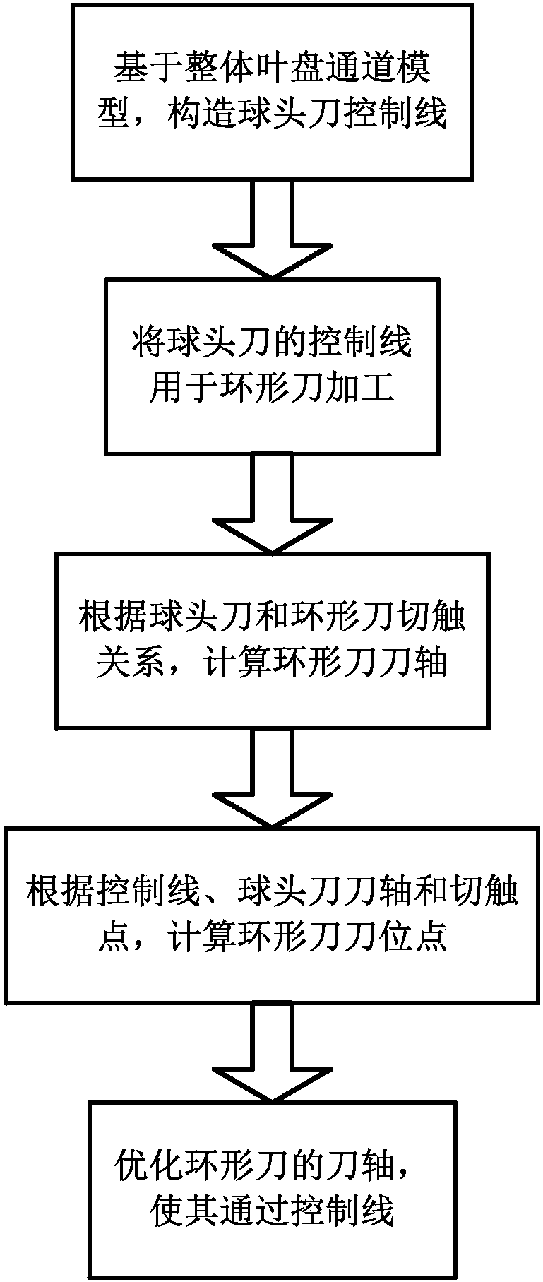
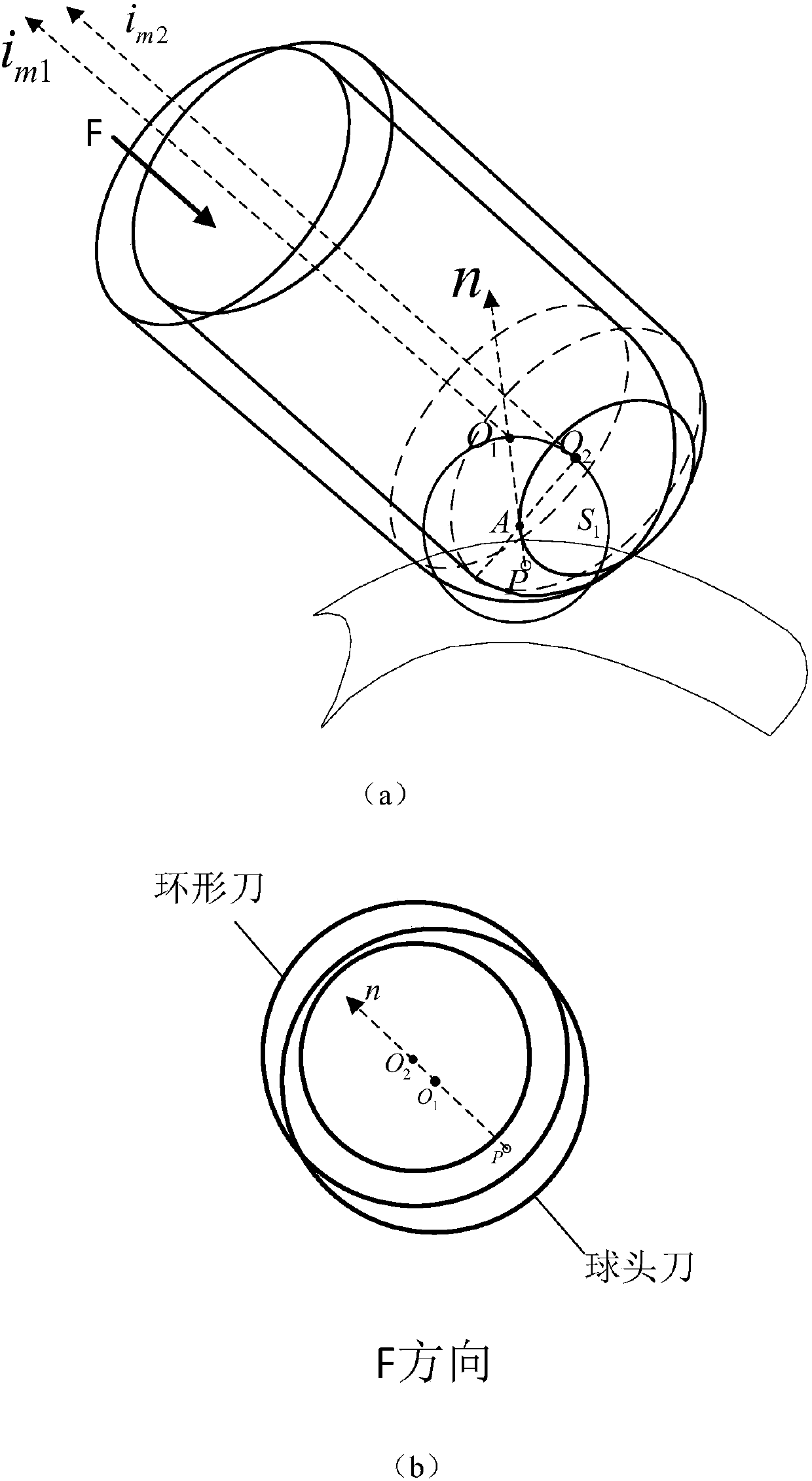
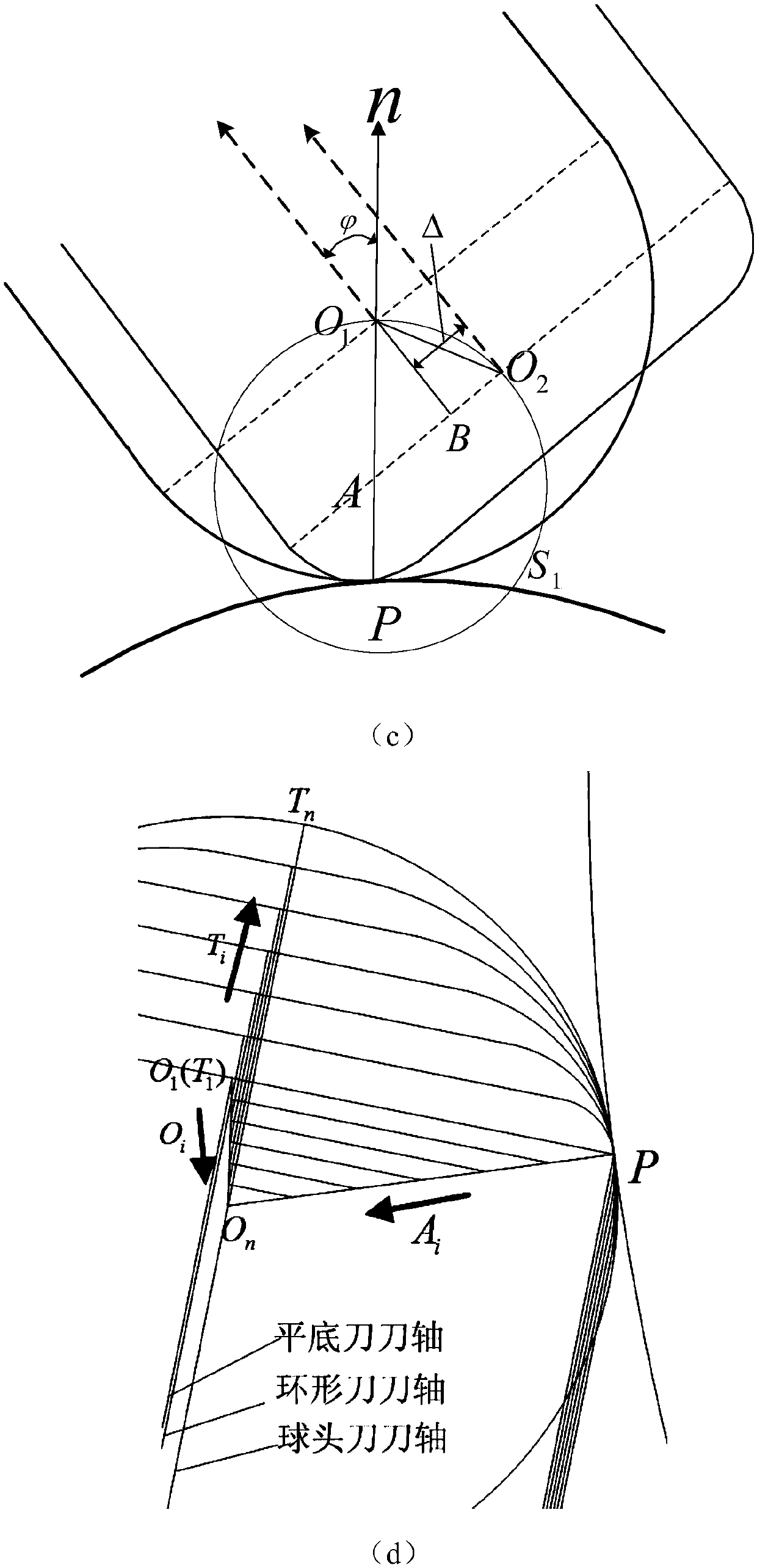
[0034] figure 1 It is the overall flow chart of the present invention. In channel processing, once the tool center point and the control line are determined, the cutter axis of the ball nose cutter is also determined immediately. The point connecting the tool center point and the control line is equal to its height direction. The shaft of the ball nose cutter. Now the ball-end cutter control line is used for ring cutter processing. Since the contact relationship between the ball-end cutter and the ring cutter is different, it is necessary to recalculate the cutter center point and the cutter axis of the ring cutter.

[0035] Step 1. According to the model of the blisk channel, construct the ball-end cutter non-interference cutter axis control line required for channel processing;

[0036] Step 2. Apply the control line of the ball head cutter to the f...


PUM


Abstract

The invention provides an aero-engine blisk annular cutter machining method based on a control line, and relates to the field of numerical control machining. By means of the control line, the cutter location point and the cutter-axis vector of an annular cutter for cutting blades of a blisk are calculated, the milling cutter location track of the blisk is planned, and the method is applied to blisk machining. According to the method, cutter path planning of blisk channel annular cutter four-axis machining based on the control line is completed, and the control line method is applied to annularcutter machining. The method remarkably improves the machining surface quality of the blisk, improves the machining efficiency and reduces working hours and the machining cost; besides, the service life of the cutter is prolonged, so that it is possible that the cutter completes machining of the surface of one blade of a large-size fan blisk before excessive abrasion, and the phenomenon that cutter connection marks are obvious due to partitioned machining is avoided.

Description

technical field [0001] The invention relates to the field of numerical control machining, in particular to a method for machining an annular cutter of an integral blisk. Background technique [0002] The low-pressure compressor fan and high-pressure compressor rotor of the new high-thrust-ratio high-performance aero-engine generally adopt an open blisk structure. The number of parts is reduced, the engine structure is greatly simplified, and the weight is reduced. Therefore, the overall blisk structure has been widely used in the aviation field. However, the overall blisk has technical characteristics such as complex structure, poor opening, thin blades, and difficult processing deformation control, which brings great difficulties to the processing of the blisk, mainly in the following aspects: (1) complex structure, open The openness is poor, the direction of the tool axis is difficult to determine, and the programming of NC machining is difficult. Most of the blisk blade...

Claims


Application Information

Patent Timeline
IPC IPC(8): G06F17/50B23C3/00
CPCB23C3/00G06F30/17
Inventor 田荣鑫任军学张晓峰姚倡锋单晨伟梁永收文学谦沈亚超
Owner NORTHWESTERN POLYTECHNICAL UNIV
Learn More