Mechanical separation device

A technology of mechanical separation and mis-separation, applied in the field of manipulators, can solve the problems of difficult control and routing of trachea and signal lines, large space occupation, poor synchronization, etc. Effect

Inactive Publication Date: 2018-02-09
岑宏华
View PDF0 Cites 5 Cited by
  • Summary
  • Abstract
  • Description
  • Claims
  • Application Information

AI Technical Summary

Problems solved by technology

[0002] At present, the unloading of products is generally completed by manipulators with complex structures. The manipulators are driven by multiple cylinders (motors). This structure is relatively complex, takes up a lot of space, has poor synchronization, slow beats, and many air pipes and signal lines are difficult to control. and wiring, high cost, clumsy structure

Method used


Image

  • Mechanical separation device

Examples


Embodiment Construction

[0012] The present invention will be described in detail below in conjunction with the accompanying drawings.

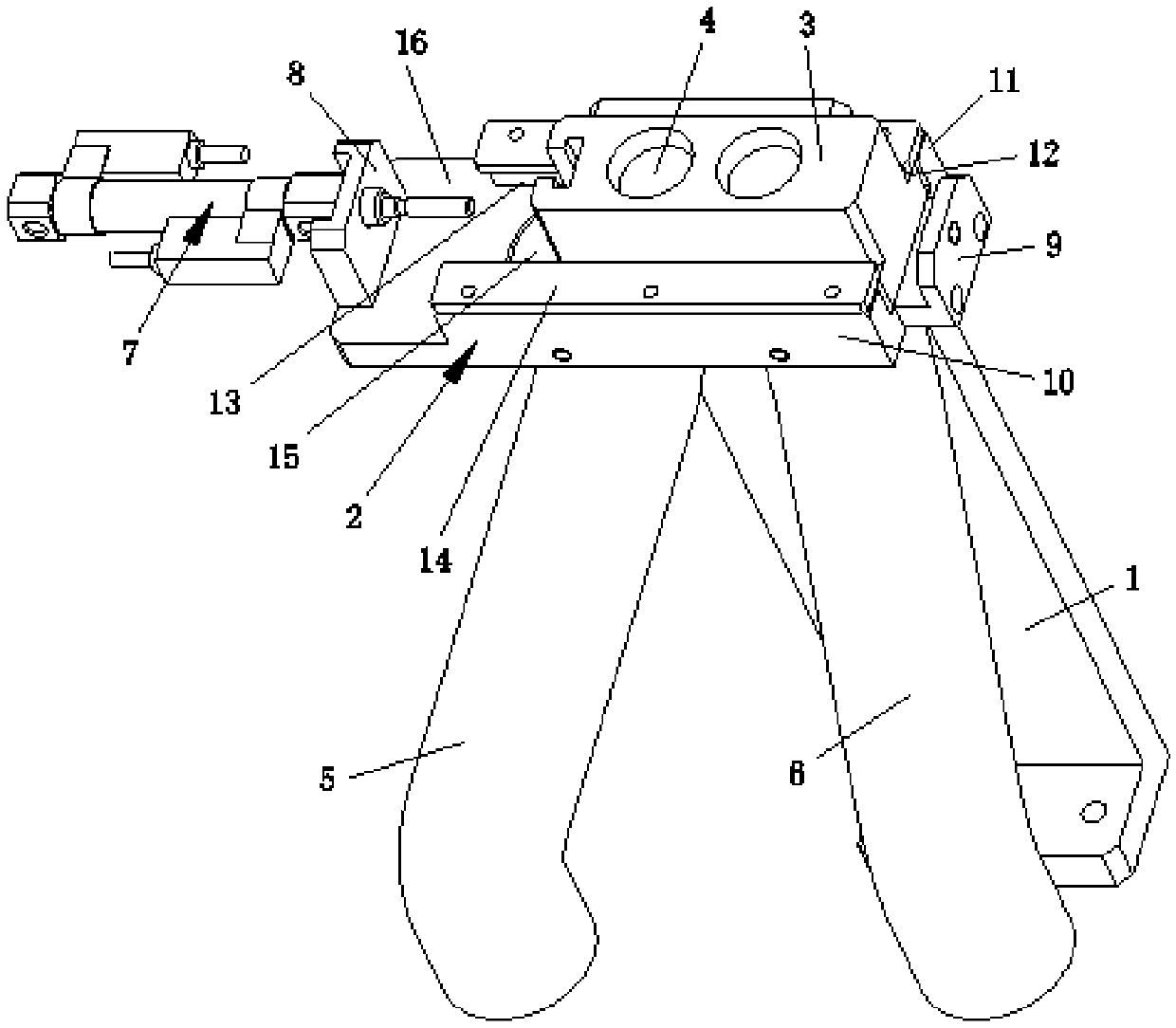
[0013] Such as figure 1 As shown, a mechanical separation device includes a supporting connecting plate 81, and the upper end of the supporting connecting plate 81 is provided with a staggering mechanism, and the staggering mechanism includes a staggering base 2, and the staggering base 2 is movably connected with a staggered Block 3, the staggered block 3 is provided with a discharge port 4, and the staggered base 2 is provided with a dislocation hole 15 cooperating with the discharge port 4, and the dislocation hole 15 is connected with a good product discharge channel 5 and the defective product discharge channel 6, one end of the staggered base 2 is connected with a staggered cylinder 7; the present invention is simple in structure, saves space, and when in use, the product is put into the discharge port 4 through the mechanism, and the staggered cylinder 7 is de...


PUM


Abstract

The present invention relates to the technical field of manipulators, in particular to a mechanical separation device, which includes a supporting connecting plate, and a staggering mechanism is arranged on the upper end of the supporting connecting plate, and the staggering mechanism includes a staggering base, and the staggering base is movably connected There are staggered blocks, the staggered blocks are provided with a discharge port, and the staggered base is provided with a dislocation hole cooperating with the discharge port, and the dislocation hole is connected with a good product discharge channel and a defective product discharge One end of the staggered base is connected with a staggered cylinder; the invention is simple in structure and saves space. When in use, the product is put into the discharge port through the mechanism, and the staggered cylinder drives the staggered blocks in the staggered base according to the detection results. Move, make the product fall into the feeding channel, realize the separation and feeding of good products and bad products, so as to achieve good synchronization, fast beat, less power, save a lot of air pipes and signal lines, simple and convenient control, beautiful wiring, and low cost Purpose.

Description

technical field [0001] The invention relates to the technical field of manipulators, in particular to a mechanical separation device. Background technique [0002] At present, the unloading of products is generally completed by manipulators with complex structures. The manipulators are driven by multiple cylinders (motors). This structure is relatively complex, takes up a lot of space, has poor synchronization, slow beats, and many air pipes and signal lines are difficult to control. And wiring, high cost, clumsy structure. Contents of the invention [0003] The purpose of the present invention is to provide a mechanical separation device, which has the characteristics of simple structure, space saving, good synchronization, fast beat, less power, saving a lot of air pipes and signal lines, simple and convenient control, beautiful wiring, and low cost. [0004] To achieve the above object, the present invention adopts the following technical solutions: [0005] A mechani...

Claims


Application Information

Patent Timeline
Patent Type & Authority Applications(China)
IPC IPC(8): B07C5/34B07C5/36
CPCB07C5/34B07C5/362
Inventor 岑宏华
Owner 岑宏华
Why Eureka
Try Eureka