Efficient groove treating and automatic slag removing steel plate cutting machine

A technology of cutting machine and steel plate, applied in the field of cutting machine and steel plate cutting machine, can solve the problems of reducing processing efficiency and productivity, increasing the labor intensity of operators, increasing operating costs and time, etc., to reduce processing efficiency and expand use performance. , The effect of reducing the complexity of processing

Active Publication Date: 2018-02-09
SHANGHAI HONGPU STEEL STRUCTURE ENG
View PDF9 Cites 2 Cited by
  • Summary
  • Abstract
  • Description
  • Claims
  • Application Information

AI Technical Summary

Problems solved by technology

However, the traditional steel plate cutting machine needs to be beveled, slag removed and welded after cutting, which not only wastes a lot of manpower and material resources, but also has low efficiency, which can no longer meet the fast-paced development of today's society and the needs of bridge construction.
[0007] Moreover, after the traditional steel plate cutting machine unloads, the cutting slag on the cutting edge of the cut plate needs to be manually removed
However, this process not only increases the labor intensity of the operator, but also takes up a lot of man-hours, reduces processing efficiency and productivity, increases operating costs and time, and indirectly affects the progress of bridge construction.

Method used


Image

  • Efficient groove treating and automatic slag removing steel plate cutting machine
  • Efficient groove treating and automatic slag removing steel plate cutting machine
  • Efficient groove treating and automatic slag removing steel plate cutting machine

Examples


Embodiment Construction

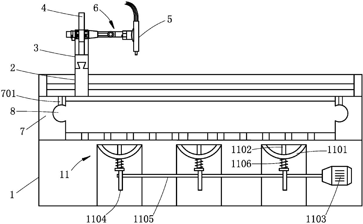
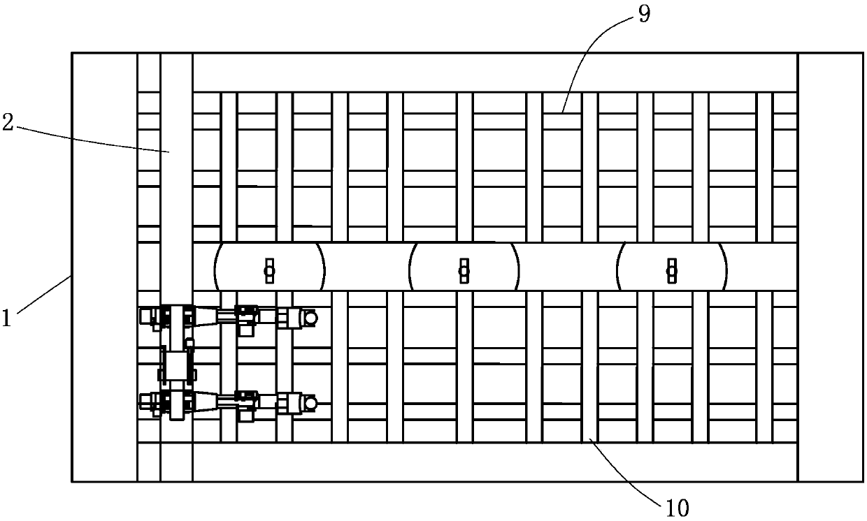
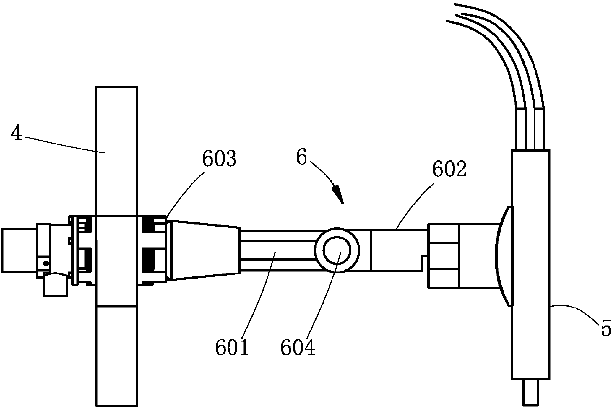
[0052] Below in conjunction with the accompanying drawings, the present invention will be described in detail through specific embodiments, but the use and purpose of these exemplary embodiments are only used to illustrate the present invention, and do not constitute any form of any limitation on the actual protection scope of the present invention, let alone The protection scope of the present invention is limited thereto.

[0053] Such as Figure 1-6 As shown together, the present invention discloses a steel plate cutting machine suitable for bridge steel plate cutting that can realize efficient groove processing and automatic slag removal. The traversing frame 2 driven by the first power device, the vertical moving frame 3 driven by the second power device is slidably installed on the traversing frame 2, and the vertical moving frame 3 driven by the third power device is slidably installed on the vertical moving frame 3. Plate 4, the cutting head 5 is installed on the lift...


PUM


Abstract

The invention discloses a steel plate cutting machine which comprises a rack. The rack is provided with a transverse movement support, a longitudinal movement support is installed on the transverse movement support and is provided with a lifting plate, a cutting head is installed on the lifting plate, and the rack is provided with a first grid plate and a second grid plate; a mechanical arm is arranged between the lifting plate and the cutting head and comprises a first transmission shaft, the first transmission shaft is connected with a first servo motor and a first connecting rod, the firstconnecting rod is provided with a second transmission shaft, a second connecting rod is connected to the second transmission shaft, and the cutting head is fixedly installed at the end of the second connecting rod; a first locking mechanism comprising a first friction sheet set is arranged between the first connecting rod and the lifting plate, and a second locking mechanism comprising a second friction sheet set is arranged between the first connecting rod and the second connecting rod; and an automatic slag removing device is installed on the lifting plate. Many beneficial effects are achieved through the unique structure design of the cutting machine, and the good application prospect and the good industrial potential productivity are achieved in the technical field of stall plate cutting.

Description

technical field [0001] The invention relates to a cutting machine, more particularly to a steel plate cutting machine with high-efficiency groove processing and automatic slag removal, belonging to the technical field of steel plate cutting and cutting devices. Background technique [0002] Generally speaking, metal cutting refers to the use of natural gas flame (oxygen-natural gas) to preheat the metal to be cut to the ignition point where it can burn or become soft, and then release a high-pressure oxygen flow to further violently oxidize the metal and melt the molten metal produced by combustion. The process of blowing off slag to form an incision. [0003] As a very important metal processing and treatment method, metal cutting has been applied in many technical fields at present, and is a very important, well-known and widely used technical method. [0004] In metal cutting, steel plate cutting is a very important category (because the application of steel is the most ...

Claims


Application Information

Patent Timeline
Patent Type & Authority Applications(China)
IPC IPC(8): B23K7/00B23K7/10
CPCB23K7/002B23K7/10B23K7/102
Inventor 严敏努
Owner SHANGHAI HONGPU STEEL STRUCTURE ENG
Why Eureka
Try Eureka