
Organic fertilizer clearance transport device

A technology of organic fertilizers and fertilizer buckets, which is applied in the field of agriculture and breeding, can solve the problems of lifting the front of the transport vehicle upwards, it is difficult to achieve the effect of dropping materials, and has great safety, so as to achieve the effect of improving operational safety

Active Publication Date: 2018-02-09
湖南省辰河生态农业科技股份有限公司
View PDF6 Cites 0 Cited by
  • Summary
  • Abstract
  • Description
  • Claims
  • Application Information

AI Technical Summary

Problems solved by technology

[0002] As we all know, the feces of some feeders can be used as the preferred organic fertilizer. In some large farms, it is necessary to use transport vehicles to regularly remove these organic fertilizers. However, the existing organic fertilizer removal devices rely on The jacking device lifts the fertilizer bucket to a certain inclination height, so as to realize the purpose of automatic dropping. However, when the fertilizer bucket is lifted upwards, the center of gravity is prone to shift and cause the front of the transport vehicle to lift upwards, which may induce a rollover accident. Possibly, there is a big potential safety hazard. At the same time, the organic fertilizer in the fertilizer bucket has a certain viscosity. It is difficult to achieve a good blanking effect only by tilting the material, and there are major disadvantages.

Method used


Image

  • Organic fertilizer clearance transport device
  • Organic fertilizer clearance transport device
  • Organic fertilizer clearance transport device

Examples


Embodiment Construction

[0021] All features disclosed in this specification, or steps in all methods or processes disclosed, may be combined in any manner, except for mutually exclusive features and / or steps.

[0022] Any feature disclosed in this specification (including any appended claims, abstract and drawings), unless expressly stated otherwise, may be replaced by alternative features which are equivalent or serve a similar purpose. That is, unless expressly stated otherwise, each feature is one example only of a series of equivalent or similar features.

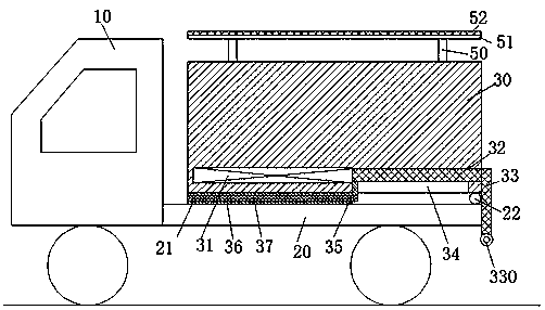
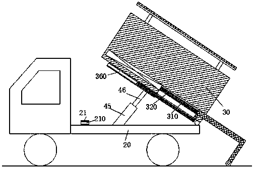
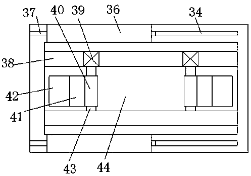
[0023] Such as Figure 1-4 As shown, an organic fertilizer removal device of the present invention includes a vehicle body 20 fixedly connected to the removal vehicle 10 and a fertilizer bucket 30 for loading organic fertilizers. The lower right end of the fertilizer bucket 30 can be moved through the first rotating rod 22 Rotatably installed on the upper right end of the vehicle body 20, the top of the fertilizer bucket 30 is provided with a...


PUM


Abstract

The invention discloses an organic fertilizer clearance transport device. The organic fertilizer clearance transport device comprises a vehicle body fixedly connected with a clearance transport vehicle, and a fertilizer barrel for containing organic fertilizers. The lower right end of the fertilizer barrel is rotationally installed at the upper right end of the vehicle body through a first rotaryrod. An installation groove with a downward opening end is formed in the bottom wall of the fertilizer barrel. Installation plates extending leftwards and rightwards are arranged on the front portionand the rear portion of the interior of the installation groove. First pushing gears are installed on the front portion and the rear portion of the upper end face of the vehicle body and internally provided with pushing rods in a matched mode, and the tails of the pushing rods are in fit connection with the installation plates. The front portion and the rear portion of the left end of the lower end wall of the vehicle body are provided with bearing blocks correspondingly, first slide cavities communicating in the left-right direction are formed in the bearing blocks, and lock rods are movablyinstalled in the first slide cavities. The front portion and the rear portion of the upper end face of the vehicle body are provided with lock blocks correspondingly, and lock grooves which communicate in the left-right direction and are matched with the lock rods are formed in the lock blocks. Second pushing gears are installed in the front end wall and the rear end wall of the installation groove correspondingly.

Description

technical field [0001] The invention relates to the field of agriculture and breeding, in particular to an organic fertilizer removal device. Background technique [0002] As we all know, the feces of some feeders can be used as the preferred organic fertilizer. In some large farms, it is necessary to use transport vehicles to regularly remove these organic fertilizers. However, the existing organic fertilizer removal devices rely on The jacking device lifts the fertilizer bucket to a certain inclination height, so as to realize the purpose of automatic dropping. However, when the fertilizer bucket is lifted upwards, the center of gravity is prone to shift and cause the front of the transport vehicle to lift upwards, which may induce a rollover accident. Possibly, there is a big potential safety hazard. At the same time, the organic fertilizer in the fertilizer bucket has a certain viscosity. It is difficult to achieve a good blanking effect only by tilting the material, and...

Claims


Application Information

Patent Timeline
IPC IPC(8): B65F3/04
CPCB65F3/046
Inventor 王亦锋
Owner 湖南省辰河生态农业科技股份有限公司
Learn More