Assembly type prefabricated hollow column

A hollow-column, prefabricated technology, applied in columns, pillars, piers, etc., can solve the problems of long solidification and hardening time, inconsistent spirit, and low cost.

Inactive Publication Date: 2018-02-09
HUNAN BDF ENERGY SAVING TECH +1
View PDF10 Cites 1 Cited by
  • Summary
  • Abstract
  • Description
  • Claims
  • Application Information

AI Technical Summary

Problems solved by technology

In order to pass the longitudinal and horizontal rib beam reinforcement through the I-beam web to form a cast-in-place hollow slab with continuous slabs, too many holes are reserved in the I-beam web and the hole diameter is too small, which is troublesome to process; at the same time, the cement hollow Long solidification and hardening time of the filling body, low mold utilization rate, high density and heavy weight of the hollow filling body, inconvenient production and transportation, poor integrity of the filling body and easy damage, etc.
[0004] In order to realize industrialized production, the inventors also applied for ZL201310332173.9 "a reticulated box-shaped component for forming holes in cast-in-place hollow floors" and ZL201510331724.X "a new type of steel-concrete composite cast-in-place hollow floors". The poured hollow floor technology has been comprehensively improved, realizing transformation and upgrading, updating and greatly reducing the self-weight of the hollow floor, adding self-insulation performance, strong structural safety, and solving the problem of realizing large-span, large space, The problems existing in the hollow floor with large loads; the inventor has continuously improved the background technology of the cast-in-place hollow floor, and laid a solid foundation for the horizontal structure of the prefabricated building with a large span and no exposed beams; although it has solved the problem of the production of hole-forming components The problem, however, is that it is poured on site, which ...

Method used


Image

  • Assembly type prefabricated hollow column
  • Assembly type prefabricated hollow column
  • Assembly type prefabricated hollow column

Examples


Embodiment Construction

[0019] The present invention will be further described below in conjunction with the accompanying drawings.

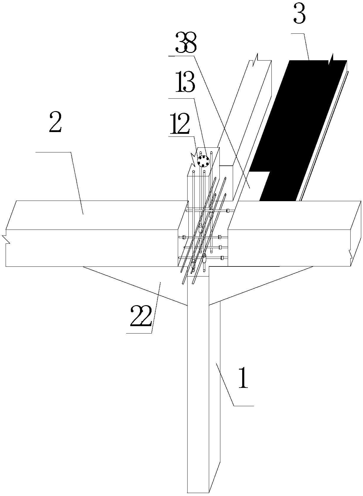
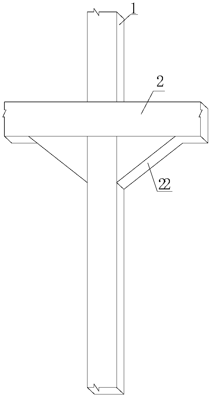
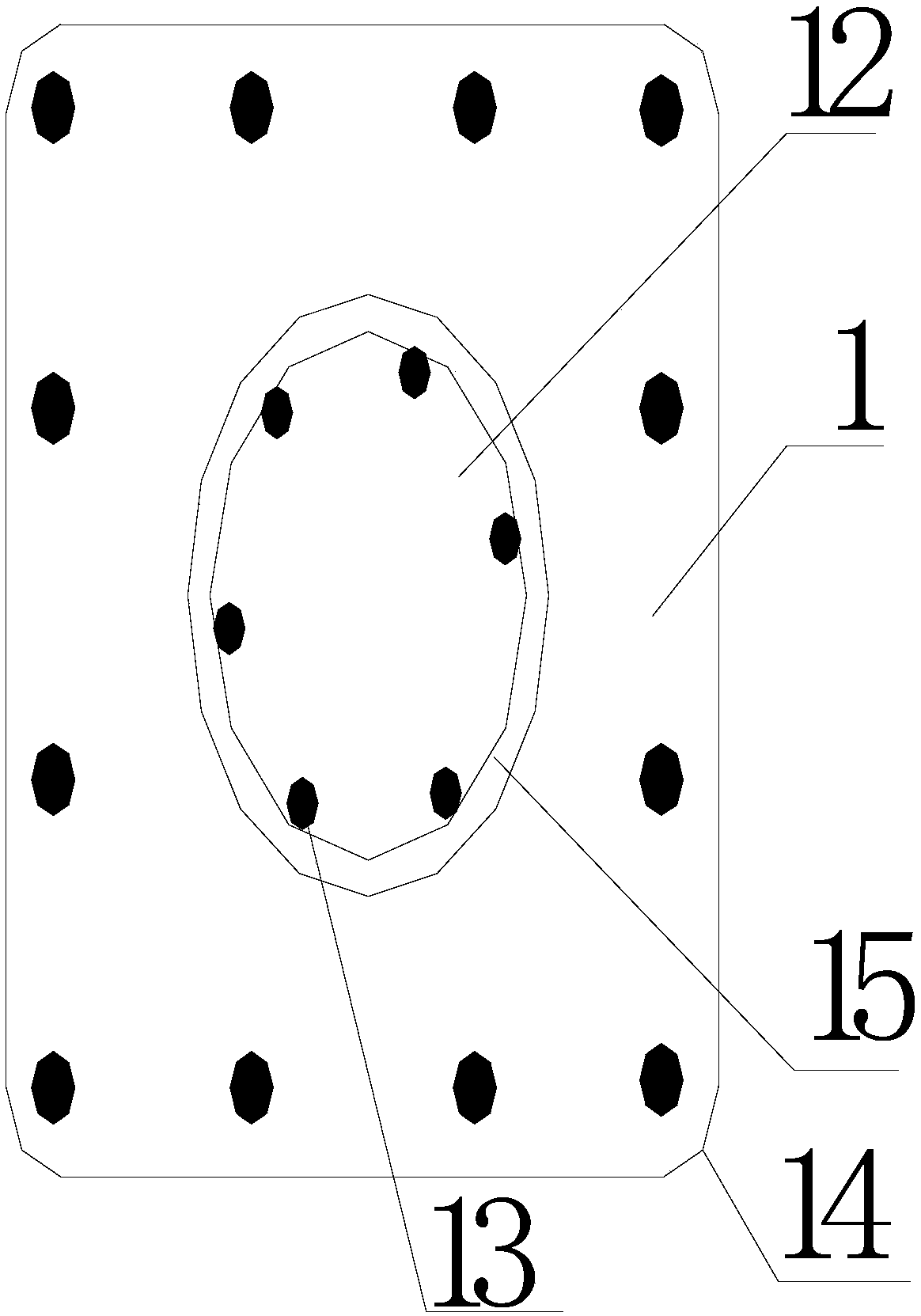
[0020] figure 1 Invented a prefabricated hollow column node diagram embodiment. When the present invention is implemented, the steel cage 13 is first connected vertically, and the connected steel cage 13 is about 1000mm higher than the prefabricated hollow column 1 to ensure the connection head of the steel cage 13 In the middle of the hollow column 1; hoist the hollow column 1, its hollow hole 12 is aligned with the steel cage 13, so that the steel cage 13 is inserted into the hollow hole 12 of the prefabricated hollow column 1; connect the upper and lower sections of the prefabricated hollow column 1 to receive vertical force Reinforcing steel, vertical force-bearing rebar The medium-length rebar is connected with the vertical force-bearing short rebar of another section of the prefabricated hollow column. At the connection point of the two sections of hollow columns, th...


PUM


Abstract

The invention provides an assembly type prefabricated hollow column. The middle of the prefabricated hollow column is hollow; force-bearing steel bars stretch out of the two ends of the prefabricatedhollow column; the force-bearing steel bars stretching out of the two ends of the prefabricated hollow column are different in length; the force-bearing steel bars with the different lengths are connected in a staggered mode through a mechanical connection or grouting connection method; the ends of the force-bearing steel bars are tapped or shaped before staggered connection; the stretching lengthof each force-bearing steel bar of the prefabricated hollow column is larger than 200 mm; and a reinforcement cage is inserted in the prefabricated hollow column.

Description

Technical field [0001] The invention relates to a fabricated building system technology, in particular to a fabricated prefabricated hollow column technology. Background technique [0002] The country vigorously promotes prefabricated buildings and clarifies specific implementation plans; and requires wide application in reinforced concrete frame structures, reinforced concrete frame shear wall structures, steel structures, and steel-concrete composite structural systems, clarifying the prefabricated building structures in my country System and application fields; however, the prefabricated building floor slab with large-span horizontal structure has just started, and ordinary laminated floor slabs are used. The technology has defects, the cost of prefabricated buildings is too high, and the grounding is not gas. Blocked. [0003] The prior art uses ordinary beams and slabs such as the inventor’s ZL200410082381.9 "a hollow small ribbed floor" and ZL200820126232.1 "a cast-in-place st...

Claims


Application Information

Patent Timeline
IPC IPC(8): E04B1/20E04B1/21E04C3/34
CPCE04B1/20E04B1/21E04C3/34
Inventor 李国强王本淼王海崴
Owner HUNAN BDF ENERGY SAVING TECH
Why Eureka
Try Eureka