Cavity plate component for stress island floor system

A technology of cavity slab and load-bearing island, which is applied in the direction of floor slab, building components, building structure, etc.

Inactive Publication Date: 2018-02-09
HUNAN BDF ENERGY SAVING TECH +1
View PDF16 Cites 1 Cited by
  • Summary
  • Abstract
  • Description
  • Claims
  • Application Information

AI Technical Summary

Problems solved by technology

In order to promote the healthy development of housing industrialization in our country, recently, the inventor participated in the largest-scale "fabricated large-span steel structure space without secondary beam" chaired by Tongji University, the School of Civil Engineering and Architecture of Central South University, and the National Tianjin Fire Research Institute in his own production base. cavity floor slab full-scale test", "fabricated large-span non-exposed beam reinforced concrete structure full-scale test", "fire-fighting and smoke exhaust test using prefabricated cavity floor slab" to test the innovativeness, advancement and rationality of the inventor's existing technology performance and safety; the test adopts the multi-span load compression full-scale test of the continuous strip and the full-scale test of the ultimate load loading of the prefabricated floor slab. Surrounding cantilever 1.6m, side length 11.6m, compression area 134.56m 2 , The dynamic load is 2KN, and the actual load is 22KN; the limit crack national standard is 1.5mm, and the actual crack is only 0.5mm; the limit deflection calculated according to the national standard is 168mm, and the actual deflection is 39mm; the prefabricated building has no exposed beam in the reinforced concrete structure through the test Or the safety of steel structures without secondary beams; the test verified that the one-way stressed floor components are changed into two-way stressed floors, and the single simply supported floor components are changed into continuous slab structures; the large-span Floor components combined with joint cracking, fire protection, sound insulation, perennial maintenance, assembly technology and other issues, especially the cost of prefabricated buildings has been reduced by 20%; the full-scale test of the structure has laid a solid foundation for further innovation of prefabricated buildings; however, the test Reveal the law of the internal force distribution of the prefabricated building structure, and under the premise of ensuring the safety requirements of the prefabricated building structure, there is still a lot of room for optimization in the prefabricated building technology

Method used


Image

  • Cavity plate component for stress island floor system
  • Cavity plate component for stress island floor system
  • Cavity plate component for stress island floor system

Examples


Embodiment Construction

[0024] The invention will be further described below in conjunction with the accompanying drawings.

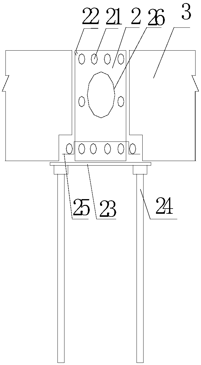
[0025] figure 1 It is an embodiment of the cross-section of the unobstructed beam floor of the prefabricated convex beam of the present invention. When the present invention is implemented, the prefabricated convex beam 2 and the bottom width of the prefabricated convex beam 2 made in the factory shall be within 600 mm, and the prefabricated convex beam 2 shall be within 600 mm. The height of 2 is within 600mm; in order to reduce the weight, a hollow beam 26 can be formed; when forming a prefabricated convex beam for a floor slab without exposed beams, the lower end of the cavity plate member is concave, and the bottom of the prefabricated convex beam 2 protrudes to a normal height It is within 100mm. At this time, ensure that the direction of the longitudinal rib beam is stressed, and the end of the steel bar at the bottom of the longitudinal rib beam is upturned by 100mm; M...


PUM


Abstract

The invention provides a cavity plate component for a stress island floor system. The cavity plate component for the stress island floor system comprises prefabricated columns, prefabricated convex beams, post caps, cavity plate component bodies, a longitudinal combined rib beam, regenerative transverse rib reinforced steel bars and a joint seam. At least two holes allowing longitudinal combined rib beam reinforced steel bars to penetrate through are reserved in the prefabricated convex beam, and thus the longitudinal combined rib beam of a continuous plate strip is formed. The post caps are arranged at the rims of the prefabricated columns and the prefabricated column at the joint of the prefabricated convex beams. The post caps are combined by the prefabricated columns, convex beam jointspaces, cavity plate component corners, auxiliary reinforced steel bars and concrete. The post caps occupy the corners of adjacent four cavity plate component bodies of the joints of the prefabricated convex beams and the prefabricated columns. Concrete is not prefabricated in the spaces above 0.15 m2 of the corners of the cavity plate component bodies, but longitudinal and transverse rib beam reinforced steel bars are exposed at the corners. Each cavity plate component body comprises a longitudinal reinforced concrete rib beam, a transverse reinforced concrete rib beam, a cavity and a lowerflange plate. The cavity plate component bodies are mounted on the two sides of the prefabricated convex beams, and have no penetrating joint seam.

Description

technical field [0001] The invention relates to a prefabricated building system technology, in particular to a cavity plate member technology used for a force-bearing island floor. Background technique [0002] In order to adjust the structure of the construction industry, improve the quality of construction, speed up construction, achieve energy conservation and environmental protection, and reduce project costs, the state has proposed to vigorously promote prefabricated buildings and specified specific implementation plans; It is widely used in wall structure, steel structure and steel-concrete composite structure system, which clarifies the structural system and application field of my country's prefabricated building; however, the prefabricated building floor with long-span horizontal structure has just started, and the common laminated floor is used , The lack of establishment of the technical system leads to high cost and ungroundedness, which restricts the development o...

Claims


Application Information

Patent Timeline
Patent Type & Authority Applications(China)
IPC IPC(8): E04B5/48E04B1/20E04B1/21
CPCE04B1/20E04B1/21E04B5/48
Inventor 李国强王本淼王海崴
Owner HUNAN BDF ENERGY SAVING TECH
Why Eureka
Try Eureka