
Engine oil tank for motorcycle with relatively good cooling property

A cooling performance, oil tank technology, applied in the direction of mechanical equipment, engine components, machines/engines, etc., can solve problems affecting backflow, high temperature fatigue of valve mechanism components, affecting the performance of valve mechanism, etc., and achieve the effect of reasonable structural design

Inactive Publication Date: 2018-02-09
邓玉平
View PDF6 Cites 0 Cited by
  • Summary
  • Abstract
  • Description
  • Claims
  • Application Information

AI Technical Summary

Problems solved by technology

If the engine is overheated, the valve is in the high temperature and high pressure condition of the gas for a long time without proper cooling, which will inevitably cause high temperature fatigue of the entire valve train components, seriously affect the performance of the valve train, and ultimately affect the overall performance and life of the engine
In the prior art, the patent CN205445715U discloses a motorcycle oil cooling device. The design height of the oil return port in the device is low, which affects the return flow. The design position of the oil filter is likely to cause residues to block the spiral oil pipe. To solve the above problems, It is a technical problem to be solved by those skilled in the art to develop a motorcycle oil tank with reasonable structure design, convenient and practical cooling performance

Method used


Image

  • Engine oil tank for motorcycle with relatively good cooling property

Examples


Embodiment 1

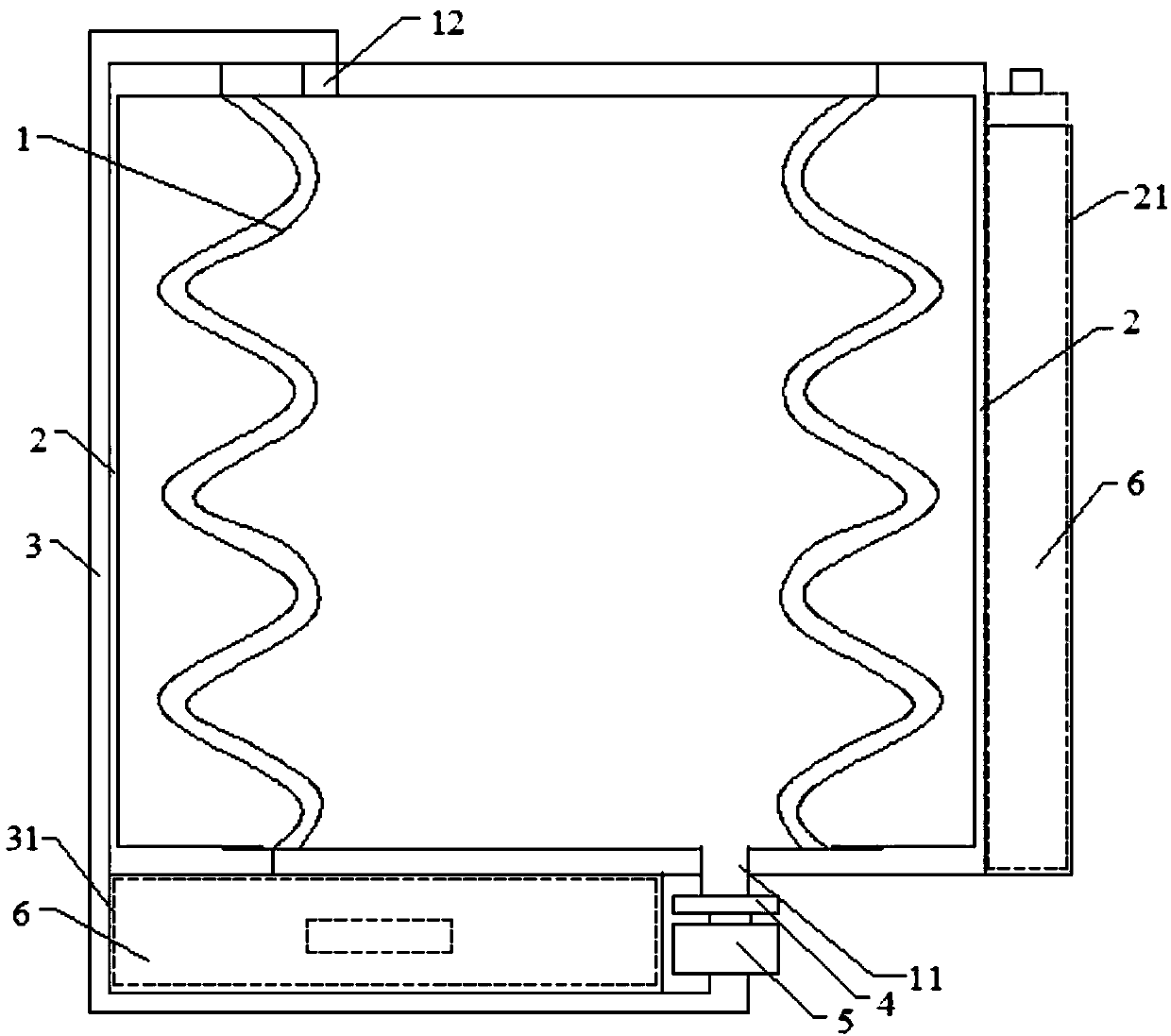
[0012] As shown in the accompanying drawing, a motorcycle oil tank with better cooling performance, the oil tank includes: a chassis 1 with a wavy cross-section, a cooling layer 2 arranged outside the chassis 1, and an oil outlet arranged at the bottom of the chassis 1 11. The oil outlet 11 is connected with the filter 4 and the oil return pump 5 sequentially through the oil return pipeline 3. The oil return pipeline 3 is connected with the oil inlet 12 arranged on the top of the chassis 1. The section of the cooling layer 2 is “[]” structure, the right side of the cooling layer 2 is provided with a first socket 21 , and a second socket 31 is provided between the bottom of the chassis 1 and the oil return pipe 3 .

[0013] Further, in the above technical solution, the cooling layer 2 is provided with a cooling liquid inlet and a cooling liquid outlet for cooling the space between the cooling layer 2 and the chassis 1, and the first socket 21 and the second socket 31 are both A...


PUM


Abstract

The invention relates to an engine oil tank for a motorcycle with a relatively good cooling property. The engine oil tank comprises a chassis with a wavy section, a cooling layer arranged on the outerside of the chassis, an engine oil port formed in the bottom of the chassis and a filter and an oil return pump which are successively connected to the engine oil outlet through an oil return pipeline; the oil return pipeline is connected to an oil inlet formed in the top of the chassis; the section of the cooling layer is of a []-shaped structure; a first spigot is arranged on the right side ofthe cooling layer; and a second spigot is arranged between the bottom of the chassis and the oil return pipeline. The engine oil tank for the motorcycle with the relatively good cooling property provided by the invention is relatively more reasonable in structural design. The design height of an oil return port does not affect reflux; an oil filter is designed on the upper portion of the pump, sothat residues are unlikely to block the oil return pipe. The first spigot and the second spigot are designed, so that the temperature of the chassis is further cooled during actual application, and the engine oil tank is convenient and practical, and is suitable for being further popularized and applied.

Description

technical field [0001] The invention relates to the technical field of structural design of an oil tank, and more specifically relates to an oil tank for motorcycles with better cooling performance. Background technique [0002] Motorcycle is a two-wheeled or three-wheeled vehicle driven by a gasoline engine. It is light, flexible, and fast-moving. It is widely used for patrolling, passenger and cargo transportation, etc. Existing ordinary motorcycles are seldom equipped with an oil cooling device, which will generate high temperature when the engine is running, and the engine oil has heat conduction properties, and continuously circulates in the engine. Therefore, if the engine oil is cooled, the cooled engine oil will cool the engine crankcase, clutch, valve components, etc. If the engine is overheated, the valve is in the high temperature and high pressure condition of the gas for a long time without proper cooling, which will inevitably cause high temperature fatigue of...

Claims


Application Information

Patent Timeline
Patent Type & Authority Applications(China)
IPC IPC(8): F01M5/00F01M11/03F01M11/00
CPCF01M5/00F01M5/002F01M11/00F01M11/03
Inventor 邓玉平
Owner 邓玉平
Learn More