Exhaust device and engine

An exhaust device and engine technology, applied in the direction of exhaust devices, engine components, machines/engines, etc., can solve the problem of easy water ingress in the exhaust pipe, achieve huge market application potential, reasonable structural design, and prolong service life Effect

Active Publication Date: 2018-02-09
SHAANXI JUZHEN POWER TECH CO LTD
View PDF3 Cites 6 Cited by
  • Summary
  • Abstract
  • Description
  • Claims
  • Application Information

AI Technical Summary

Problems solved by technology

[0005] The exhaust pipe is easy to get water;

Method used


Image

  • Exhaust device and engine
  • Exhaust device and engine
  • Exhaust device and engine

Examples


Embodiment 1

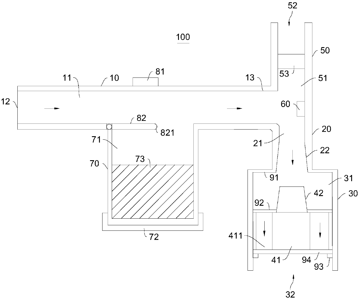
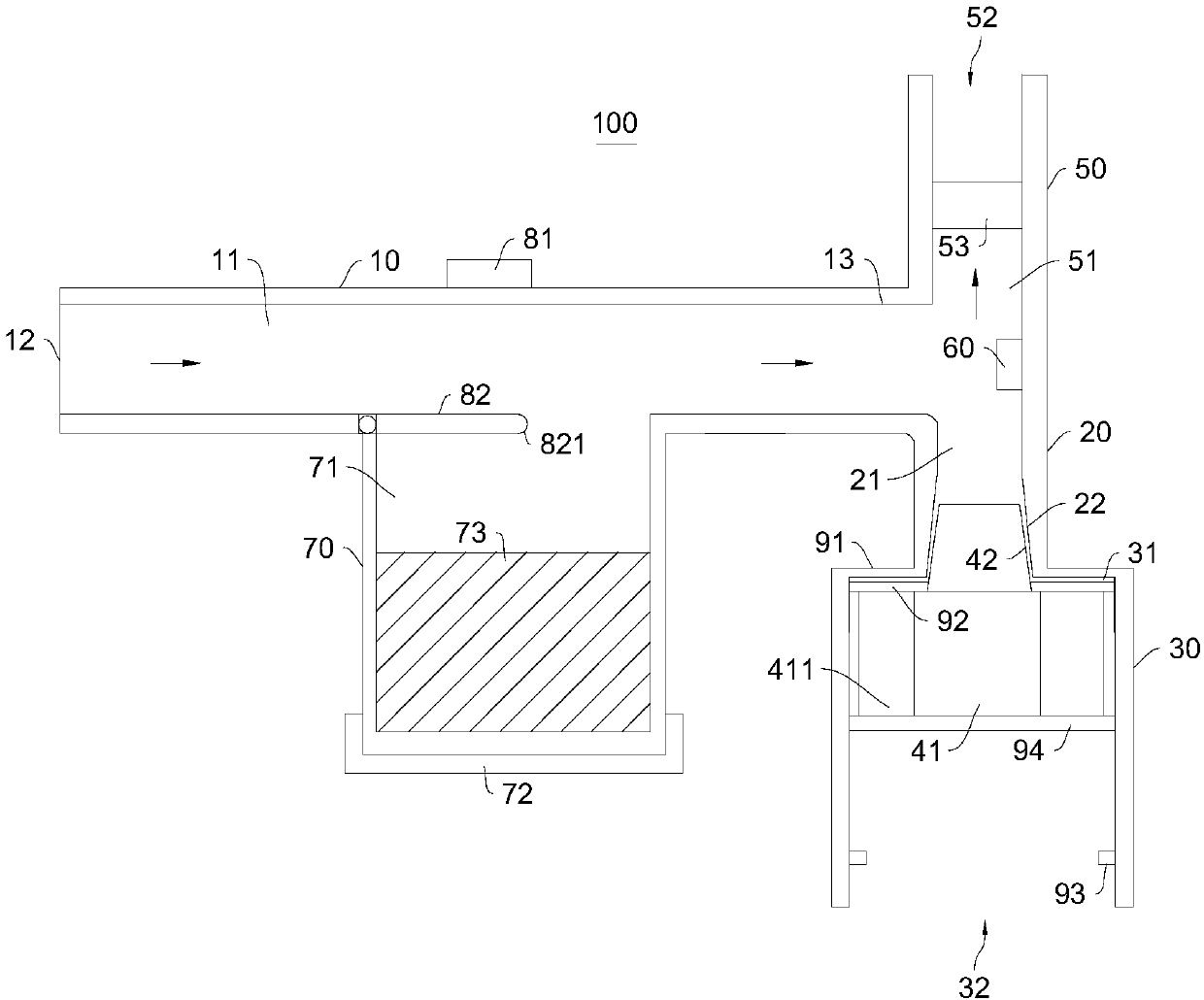
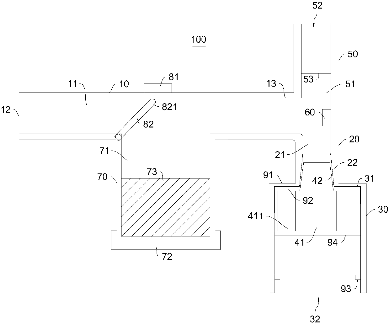
[0043] Please refer to Figure 1-Figure 4 , the present embodiment provides an exhaust device 100, which includes:

[0044] An exhaust main pipe 10, the exhaust main pipe 10 has an exhaust main channel 11, and one end of the exhaust main pipe 10 is used to communicate with the exhaust end of the engine body;

[0045] The first exhaust pipe 20, the first exhaust pipe 20 has a first exhaust passage 21, the first exhaust pipe 20 is connected to the main exhaust pipe 10 and communicates with the main exhaust passage 11 and the first exhaust passage 21;

[0046] Exhaust piece 30, the exhaust piece 30 has an exhaust chamber 31, one end of the exhaust piece 30 communicates with the first exhaust pipe 20, and the other end of the exhaust piece 30 has a first exhaust port communicated with the exhaust chamber 31 32. The opening direction of the first exhaust port 32 is vertically downward;

[0047] The floating block 40, the floating block 40 is located in the exhaust chamber 31, the f...

Embodiment 2

[0093] This embodiment also provides an engine, which includes the exhaust device 100 mentioned above, which has all the functions of the exhaust device 100 .

[0094] For the structure of the exhaust device 100, reference may be made to Embodiment 1.

[0095] The engine also includes an engine body and a silencing device. The exhaust gas produced by the engine body enters the main exhaust passage 11 after being processed by the silencing device for noise reduction.

[0096] When the above-mentioned exhaust device 100 is selected for the engine, the service life of the engine body can be effectively extended.

[0097] To sum up, the present invention provides an exhaust device 100. The exhaust device 100 adopts the design of the floating block 40. When water flows in, the floating block 40 moves up to realize sealing, preventing the exhaust pipe from entering water, thereby effectively Prevent water from flowing into the engine, effectively prolonging the service life of the ...


PUM


Abstract

The invention provides an exhaust device and an engine, and belongs to the technical field of engines. The exhaust device comprises an exhaust main pipe, a first exhaust pipe, an exhaust part and a floating block. The exhaust main pipe is provided with an exhaust main channel. One end of the exhaust main pipe is used for communicating with the exhaust end of an engine body. The first exhaust pipeis provided with a first exhaust channel. The exhaust part is provided with an exhaust chamber. One end of the exhaust part communicates with the first exhaust pipe. The other end of the exhaust partis provided with a first exhaust opening communicating with the exhaust chamber. The floating block is located in the exhaust chamber and comprises a sliding block and a closed block. The sliding block is connected to the exhaust part in a sliding manner and is provided with exhaust holes enabling the first exhaust channel to communicate with the first exhaust opening. According to the exhaust device, through the design of the floating block, after water flows into the exhaust device, the floating block moves upwards to achieve closing, water is prevented from entering the exhaust pipe, and therefore water is effectively prevented from flowing into the engine, and the service life of the engine is effectively prolonged. The engine comprises the exhaust device and has all the functions of the exhaust device.

Description

technical field [0001] The invention relates to the technical field of engines, in particular to an exhaust device and an engine. Background technique [0002] When the car is driving on a rainy day, when the water on the road surface is deep, if the car is forced to pass, the water flow may flow into the engine along the exhaust pipe, causing the engine to stall, or even causing the engine to be scrapped. [0003] Many cars are now parked in underground garages. Once there is a heavy rain, the basement is prone to water accumulation. Once it overflows the exhaust pipe, it may enter the engine along the pipe, which greatly affects the service life of the engine. [0004] The inventor found in the research that there are at least the following disadvantages in the traditional automobile use process: [0005] The exhaust pipe is easy to get water; [0006] The engine stalls easily. Contents of the invention [0007] The purpose of the present invention is to provide a kin...

Claims


Application Information

Patent Timeline
Patent Type & Authority Applications(China)
IPC IPC(8): F01N13/08F01N13/00
CPCF01N13/008F01N13/08F01N13/085F01N2560/08
Inventor 白云龙
Owner SHAANXI JUZHEN POWER TECH CO LTD
Why Eureka
Try Eureka