Volute fan for smoke exhaust ventilator

A technology of volute fan and range hood, applied in the direction of oil fume removal, machine/engine, application, etc., can solve the problems of unfavorable atmospheric environment, small exhaust volume of volute fan, unstable air flow, etc., and achieve oil and gas air flow system Stable, improve smoke exhaust efficiency, reduce the effect of cleaning difficulty

Pending Publication Date: 2018-02-09
佛山市美家生活电器有限公司
View PDF0 Cites 2 Cited by
  • Summary
  • Abstract
  • Description
  • Claims
  • Application Information

AI Technical Summary

Problems solved by technology

[0003] (1) The structural design of the volute fan in the existing range hood is unreasonable, resulting in a small exhaust volume of the volute fan, thereby reducing the smoke exhaust efficiency of the range hood, and a large amount of oil fume is not removed in time and is distributed to Indoors, the smell of lampblack seriously affects people's life and work, as well as affects people's health
[0004] (2) In addition, the volute fan is used for a long time, and the oil accumulates at the bottom of the volute of the volute fan, which is not clean and hygienic, and it is very difficult to clean
[0005] (3) What's more, the existing range hoods directly discharge the oil fumes into the atmosphere, and a large amount of oil fumes are directly discharged into the air without treatment, which in turn affects the adjacent air, which is not conducive to the atmospheric environment and environmental protection
[0006] (4) The volute fan in the existing range hood also uses double centrifugal wind wheels, but the double centrifugal wind wheels blow in the same direction. Although the double centrifugal wind wheels increase the exhaust air volume, the air flow Unstable, prone to collisions, increased noise

Method used


Image

  • Volute fan for smoke exhaust ventilator
  • Volute fan for smoke exhaust ventilator
  • Volute fan for smoke exhaust ventilator

Examples


Embodiment Construction

[0026] The present invention will be further described below in conjunction with the accompanying drawings and embodiments.

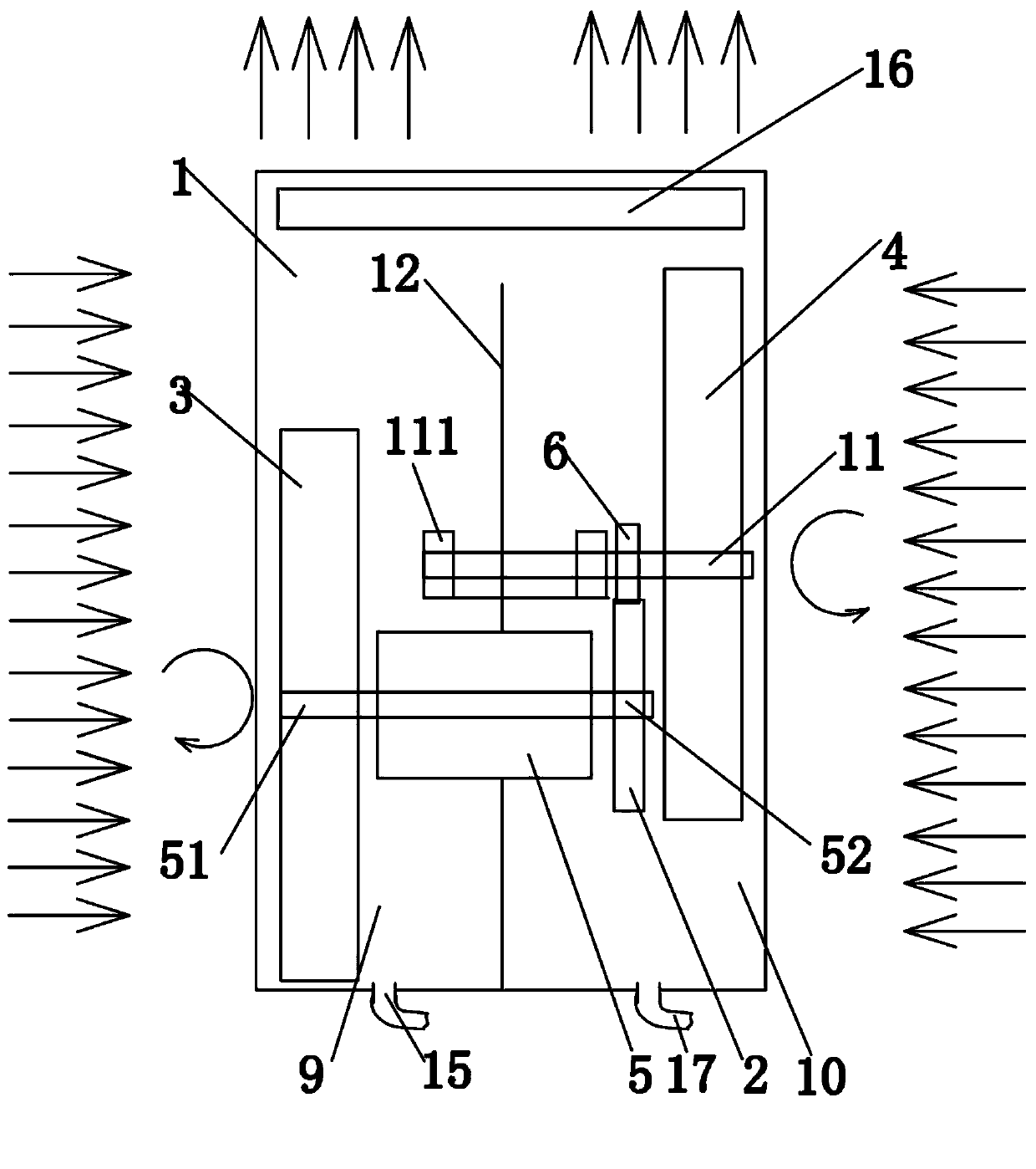
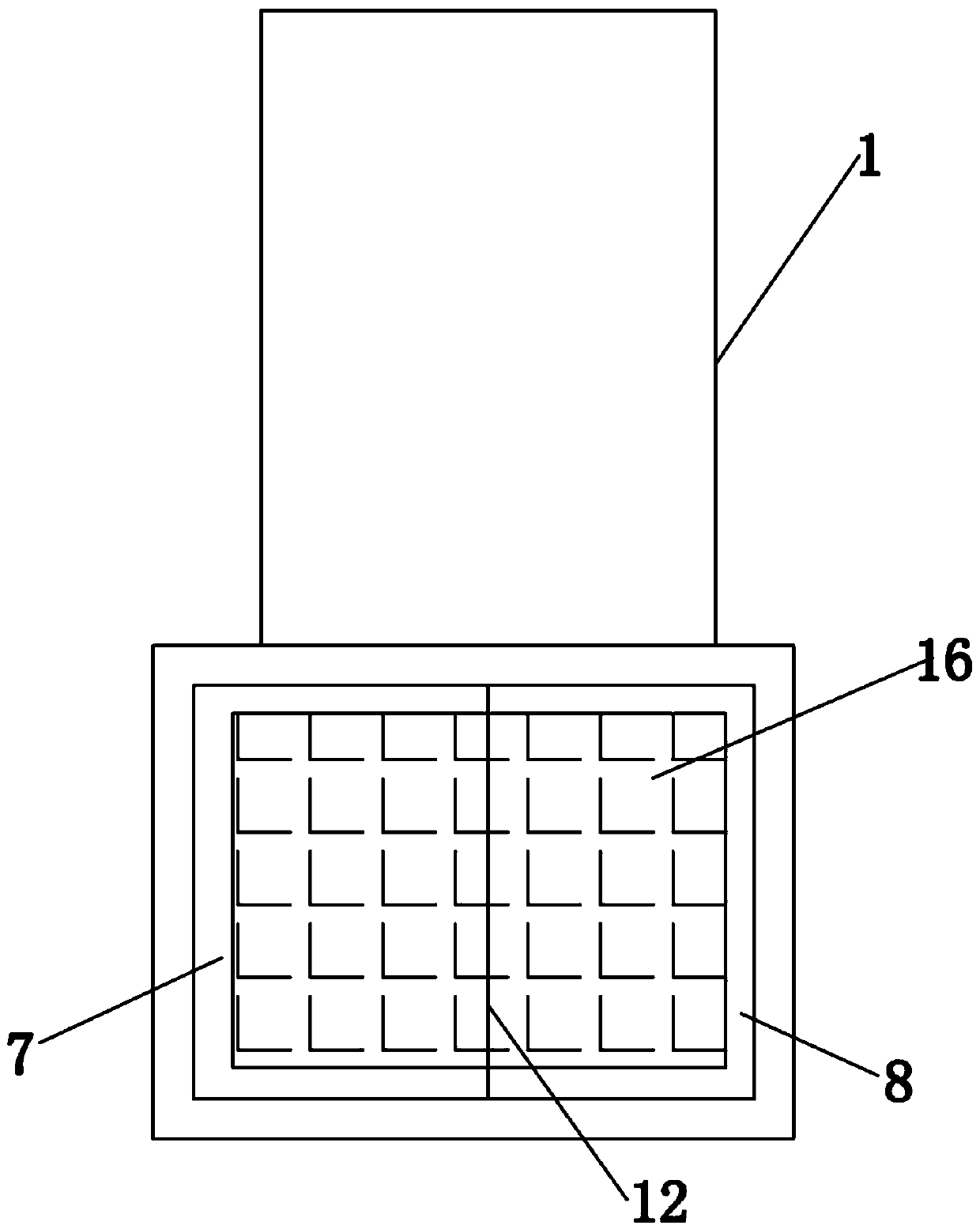
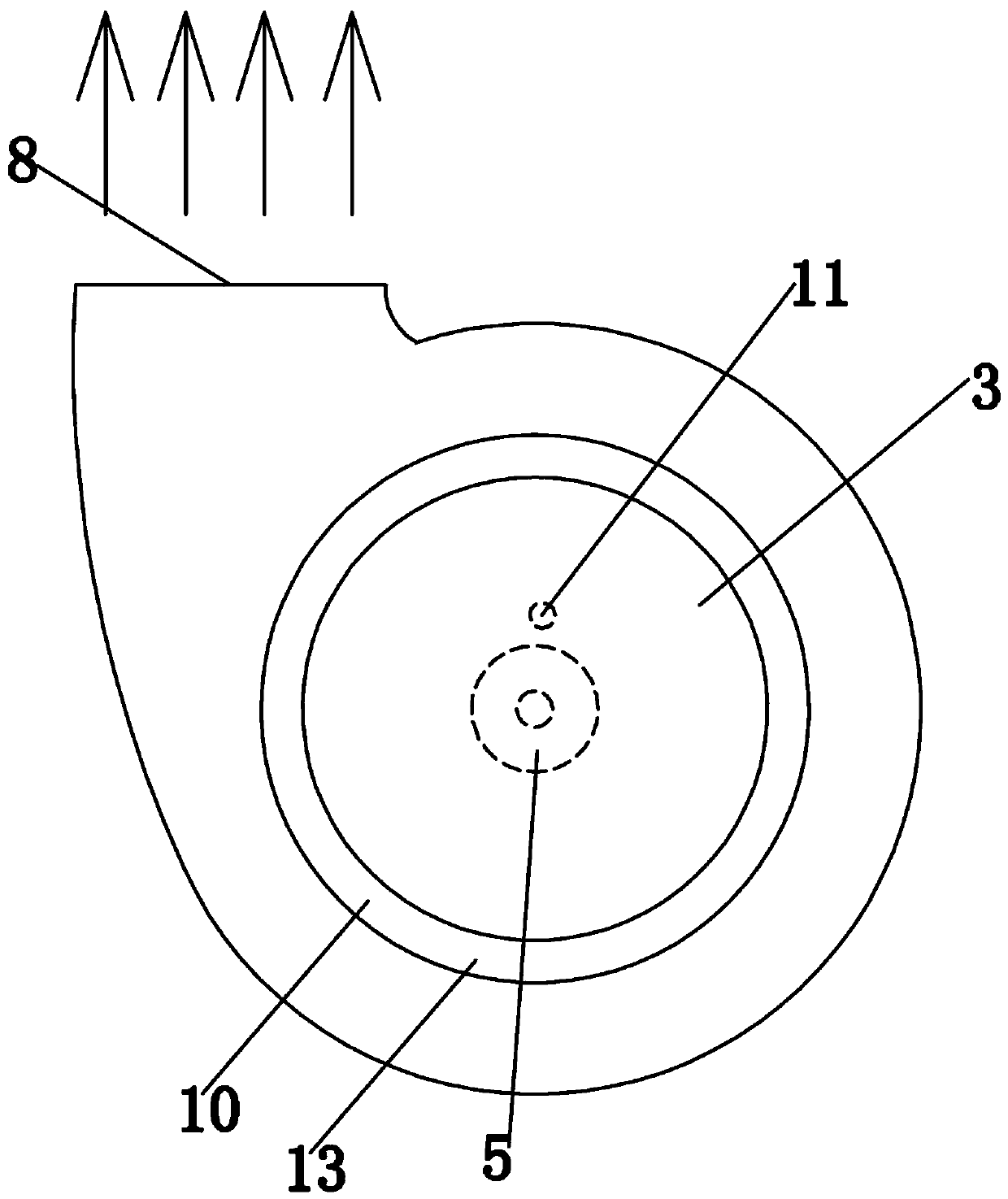
[0027] see Figure 1 to Figure 5 As shown, a volute fan for range hoods includes a volute 1, a double output shaft motor 5, a first centrifugal fan 3 and a second centrifugal fan 4, and a partition 12 is arranged inside the volute 1 , the partition 12 divides the volute 1 into a first wind chamber 9 and a second wind chamber 10, and the first centrifugal wind wheel 3 and the second centrifugal wind wheel 4 are respectively located in the first wind chamber 9 and the second wind chamber 10 , the double output shaft motor 5 is arranged on the partition 12, the first and second output shafts 51, 52 of the double output shaft motor 5 extend to the first wind chamber 9 and the second wind chamber 10 respectively, the The first output shaft 51 of the double output shaft motor 5 is drivingly connected to the first centrifugal wind wheel 3, the second output s...


PUM


Abstract

The invention relates to a volute fan for a smoke exhaust ventilator. The volute fan comprises a volute, a double-output-shaft motor, a first centrifugal wind wheel and a second centrifugal wind wheel. A partition plate is arranged inside the volute. The volute is divided into a first wind cavity and a second wind cavity through the partition plate. A second output shaft of the double-output-shaftmotor is provided with a first transmission gear. A second transmission gear and a rotating shaft are arranged in the second wind cavity. The first transmission gear is engaged with the second transmission gear. The second transmission gear is in transmission connection with the inner end of the rotating shaft, and the outer end of the rotating shaft is in transmission connection with the secondcentrifugal wind wheel. Compared with a volute fan in an existing smoke exhaust ventilator, the double centrifugal wind wheels are adopted in the volute fan for blowing air, and therefore the air exhaust amount of the volute fan is increased and finally the smoke exhaust efficiency of the smoke exhaust ventilator is improved. Moreover, an oil discharging hole is formed in the bottom of the volute,oil cannot be left inside the volute easily, cleanliness and sanitation of the volute fan are guaranteed, peculiar smells are avoided and meanwhile the cleaning difficulty of users is lowered.

Description

technical field [0001] The invention relates to a range hood, in particular to a volute fan for the range hood. Background technique [0002] Range hood, also known as range hood, is a kitchen appliance that purifies the kitchen environment. It is installed above the healthy and energy-saving range hood stove in the kitchen. It can quickly take away the waste burned by the stove and the oil fume harmful to the human body produced during the cooking process, and discharge it to the outside, reduce pollution, purify the air, and have anti-virus and explosion-proof safety guarantees. effect. As the core component of the range hood, the volute fan mainly plays the role of exhausting the range hood. However, the existing volute fans have the following disadvantages: [0003] (1) The structural design of the volute fan in the existing range hood is unreasonable, resulting in a small exhaust volume of the volute fan, thereby reducing the smoke exhaust efficiency of the range hoo...

Claims


Application Information

Patent Timeline
IPC IPC(8): F04D29/42F04D29/30F24C15/20
CPCF04D29/30F04D29/4226F24C15/20
Inventor 叶建利
Owner 佛山市美家生活电器有限公司
Why Eureka
Try Eureka