Light transmission plate and panel lamp

A technology of light-transmitting plate and panel light, which is applied in the direction of light source fixing, lighting device, and components of lighting device, etc., can solve the problems of increasing cost, increasing lens, and making the thickness of the backlight source thinner, so as to reduce the demand space. , Improve the utilization rate of light energy, increase the effect of using places and scope

Active Publication Date: 2018-02-09
PEPNICE ELECTRONIC SCI & TECH CO LTD
View PDF10 Cites 7 Cited by
  • Summary
  • Abstract
  • Description
  • Claims
  • Application Information

AI Technical Summary

Problems solved by technology

The disadvantage is that the lens is added, and the thickness of the backlight cannot be made thinner
At the same time, the lens increases the cost

Method used


Image

  • Light transmission plate and panel lamp
  • Light transmission plate and panel lamp
  • Light transmission plate and panel lamp

Examples


Embodiment 1

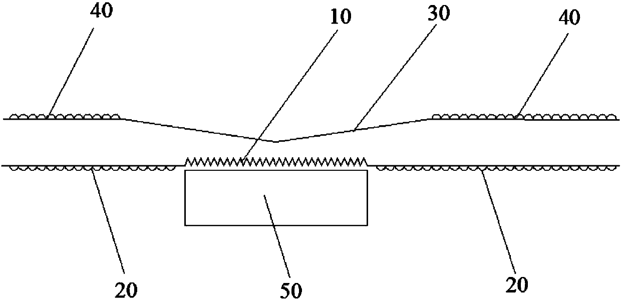
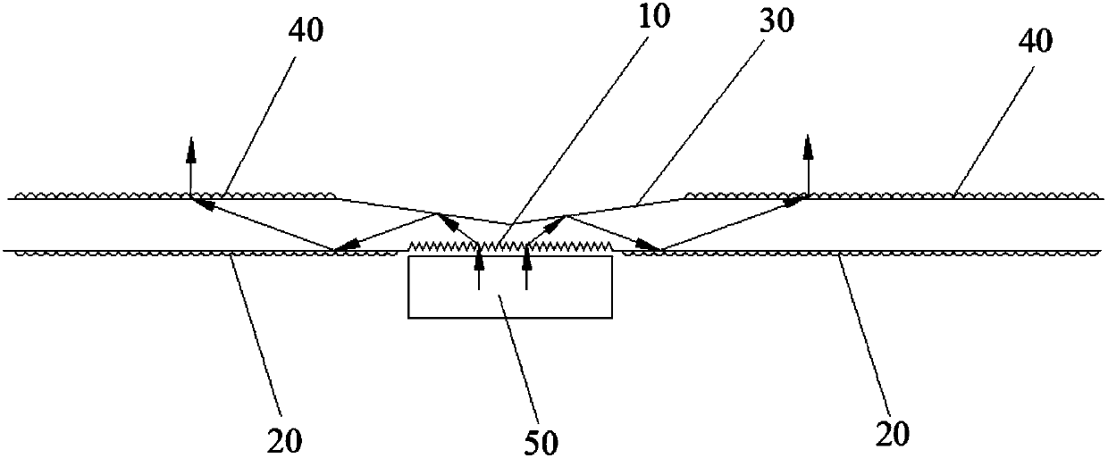
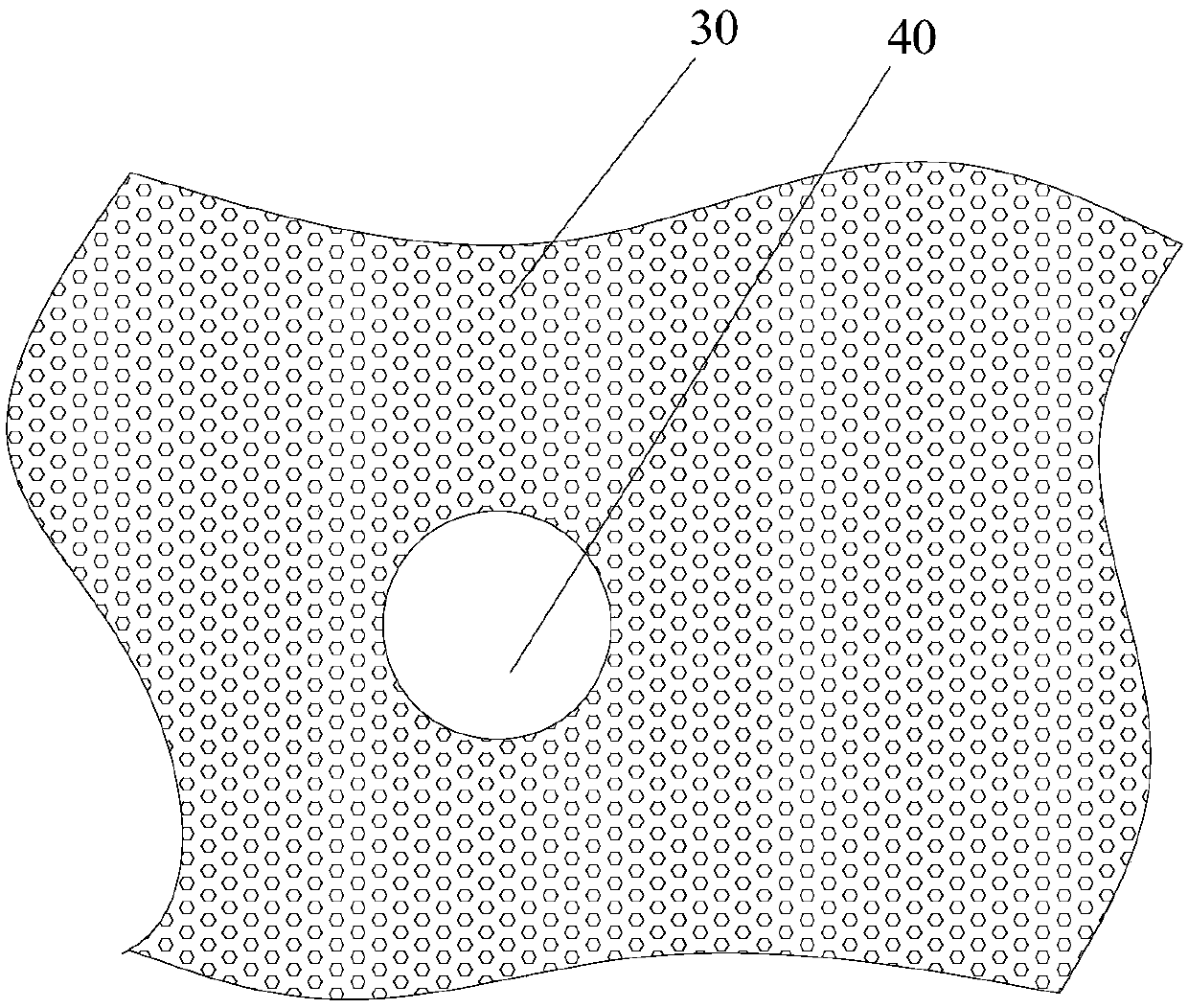
[0028] Such as Figure 1 to Figure 5 As shown, the light-transmitting plate of the present application, in one embodiment, the lower surface of the light-transmitting plate is provided with an optical scattering structure 10 and an optical reflection structure 20, and the upper surface of the light-transmitting plate is provided with an optical polarization structure 30 and an optical focusing structure. Structure 40. In the present application, the lower surface of the light-transmitting plate is the light incident end, and the upper surface of the light-transmitting plate is the light-emitting end. The optical reflective structure 20 surrounds the optical scattering structure 10, the optical polarizing structure 30 cooperates with the optical scattering structure 10, the optical concentrating structure 40 surrounds the optical polarizing structure 30, the light-transmitting plate can be used to be installed on the optical path, and the optical The scattering structure 10 co...

Embodiment 2

[0036] The panel light of the present application includes a light source 50 and a light-transmitting plate. Such as Figure 1 to Figure 5As shown, in one embodiment, an optical scattering structure 10 and an optical reflection structure 20 are provided on the lower surface of the transparent plate, and an optical polarizing structure 30 and an optical concentrating structure 40 are provided on the upper surface of the transparent plate. In the present application, the lower surface of the light-transmitting plate is the light incident end, and the upper surface of the light-transmitting plate is the light-emitting end. The optical reflective structure 20 surrounds the optical scattering structure 10, the optical polarizing structure 30 cooperates with the optical scattering structure 10, the optical concentrating structure 40 surrounds the optical polarizing structure 30, the light-transmitting plate can be used to be installed on the optical path, and the optical The scatte...


PUM


Abstract

The invention discloses a light transmission plate and a panel lamp. An optical scattering structure and an optical reflecting structure are arranged on the lower surface of the light transmission plate; the optical reflecting structure surrounds the optical scattering structure; an optical polarizing structure and an optical condensing structure are arranged on the upper surface of the light transmission plate; the optical polarizing structure is matched with the optical scattering structure; the optical scattering structure is matched with a light source; light rays emitted by the light source are steered to enter the light transmission plate through a light ray scattering structure, and are deflected onto the optical reflecting structure through the optical polarizing structure; and theoptical reflecting structure enables the reflected light rays to irradiate to the optical condensing structure and to emit out through the optical condensing structure. The light transmission plate can be machined on a transparent plate; the light source, such as an LED and the like is directly bonded on the light transmission plate, so that the light rays emitted by the light transmission platecan be displayed as uniform planar light, the material cost is reduced, the utilization rate of light energy is increased, and the input power is reduced; and meanwhile, photoelectric products can bethinner, so that the demand space is reduced, and the use places and ranges are widened.

Description

technical field [0001] The present application relates to a lamp, in particular to a light-transmitting board and a panel lamp. Background technique [0002] The current planar light emitting products use point light sources or linear light sources or surface light sources composed of point light sources and linear light sources. The area of ​​these light sources is smaller than the area that requires planar light output. [0003] For example, there are three ways to use flat panel lights for lighting. The first way is that the light source is placed on the side of the lamp, through the reflection plate, the light guide plate, and the diffusion plate, and then the light is emitted from the plane of the diffusion plate. The advantage of this structure is that the light output from the plane is relatively uniform, but the disadvantage is that the cost is high and a variety of materials are needed to solve it. The weight is heavy, and the accumulated weight of various material...

Claims


Application Information

Patent Timeline
Patent Type & Authority Applications(China)
IPC IPC(8): F21V5/00F21V7/22F21V19/00
CPCF21V5/00F21V7/22F21V19/00
Inventor 蒋泽全胡建伟
Owner PEPNICE ELECTRONIC SCI & TECH CO LTD
Why Eureka
Try Eureka