Base station antenna and wave beam shaping method therefor

A base station antenna and beam shaping technology, applied in the directions of antenna, antenna coupling, antenna array, etc., can solve the problems of the horizontal half power angle not meeting the design index, the half power angle is too narrow, and the optimization parameters are too many, so as to facilitate batch deployment, The effect of improving consistency and expanding the design range

Active Publication Date: 2018-02-09
TONGYU COMM INC
View PDF8 Cites 3 Cited by
  • Summary
  • Abstract
  • Description
  • Claims
  • Application Information

AI Technical Summary

Problems solved by technology

Although this design method can make the overall performance of the antenna meet the standard, however, the design is difficult, there are many optimization parameters, and there are many uncertain factors, especially when the antenna size and performance requirements are relatively strict, it is difficult to meet all requirements at the same time only through the optimization boundary. item indicator
Simply relying on the optimized boundary, in many cases the horizontal half-power angle is too wide to meet the design specifications; using a common 3dB bridge, "borrowing" a unit from another channel to compress the wave width will make the half-power angle too narrow, and at the same time cause Severe beam distortion

Method used


Image

  • Base station antenna and wave beam shaping method therefor
  • Base station antenna and wave beam shaping method therefor
  • Base station antenna and wave beam shaping method therefor

Examples


Embodiment Construction

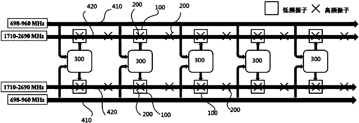
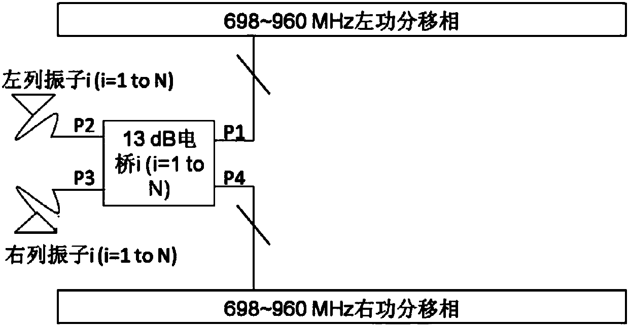
[0027] see figure 1 , a schematic diagram of an embodiment of the base station antenna of the present invention, which includes at least two independently electrically adjustable radiating element arrays, each of which includes a high-frequency radiating element 200 and a low-frequency radiating element 100, and the dual-frequency coaxial array antenna also includes The cables 410 and 420 for feeding the high-frequency radiation unit and the low-frequency radiation unit respectively, wherein the cable 410 for feeding the low-frequency radiation unit 100 is connected to the low-frequency wires in the two rows of radiation unit arrays through the weak coupling bridge 300 The radiating elements are connected, and the beams of the radiating elements are shaped through the weak coupling bridge 300 . Furthermore, the weak coupling bridge 300 is connected to the phase shifters of the feed cables of the two antenna arrays. The low-frequency radiation unit mentioned herein may be a me...


PUM


Abstract

The invention provides a wave beam shaping method for a base station antenna, and the method comprises the steps: enabling corresponding array elements of two antenna arrays at different channels to achieve the wave beam overlapping through a weak coupling bridge, wherein the four ports of the weak coupling bridge are respectively connected with feed cables of the two antenna arrays and the corresponding array elements of the two antenna arrays, thereby forming two-element subarrays; enabling the array element at the other channel to feed weak electric signals through coupling ends for excitation when the weak coupling bridge is employed for the wave beam shaping of the two-element subarrays and one channel is a use channel; enabling the array elements at the other channel to be overlappedwith corresponding array elements in a main feed column at the use channel through wave beams, thereby achieving a needed horizontal half-power angle. The method creatively proposes a mode of building grouped two-element subarrays through the weak coupling bridge, and achieves the needed horizontal half-power angle through the optimization of the combination configuration scheme of the two-element subarrays. The method remarkably improves the consistency of the horizontal half-power angle, enlarges the design section of the horizontal half-power angle, and improves the front-to-rear ratio andcross polarization of an antenna to a certain extent.

Description

【Technical field】 [0001] The present invention relates to the technical field of communications, in particular to a base station antenna and a beam shaping method thereof. 【Background technique】 [0002] With the development of miniaturization, the isolation of multi-channel antennas has become a technical problem in the design of base station antennas: on the one hand, the width of the reflector is getting narrower, resulting in smaller channel spacing and poorer isolation between systems; on the other hand, different The coupling between channel elements seriously affects the radiation pattern of the antenna, such as: widening of the horizontal half-power angle, decrease in gain, deterioration of front-to-back ratio, and deterioration of cross-polarization, etc. The development of communication technology has put forward higher and higher requirements for the shape of the radiation beam. For the macro base station antenna, not only must meet the requirements of gain and do...

Claims


Application Information

Patent Timeline
Patent Type & Authority Applications(China)
IPC IPC(8): H01Q1/52H01Q21/00
CPCH01Q1/521H01Q21/00
Inventor 丁文王国奇吴中林岳彩龙
Owner TONGYU COMM INC
Why Eureka
Try Eureka