
Millimeter wave broadband corrugated horn and manufacturing method thereof

A corrugated speaker and millimeter-wave technology, applied in the direction of waveguide speakers, radiation element structure, electrical components, etc., can solve the problems of high difficulty in processing ring loading grooves, affecting telecommunications performance, and easily generating high-order modes, etc.

Active Publication Date: 2020-10-20
ANHUI SUN CREATE ELECTRONICS
View PDF11 Cites 0 Cited by
  • Summary
  • Abstract
  • Description
  • Claims
  • Application Information

AI Technical Summary

Problems solved by technology

[0003] In the millimeter wave frequency band, the corrugated speaker with broadband matching is realized, and the main mode of the circular waveguide is TE 11 Modulo conversion to HE 11 The variable mode section of the mold mostly adopts the ring loading slot structure. The processing difficulty of the ring loading slot in the millimeter wave frequency band is relatively high, and the processing technology is complicated, which is easy to produce high-order modes, which affects the performance of telecommunications.

Method used


Image

  • Millimeter wave broadband corrugated horn and manufacturing method thereof
  • Millimeter wave broadband corrugated horn and manufacturing method thereof
  • Millimeter wave broadband corrugated horn and manufacturing method thereof

Examples


Embodiment 1

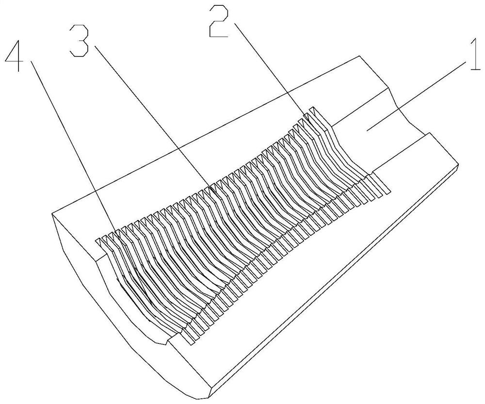
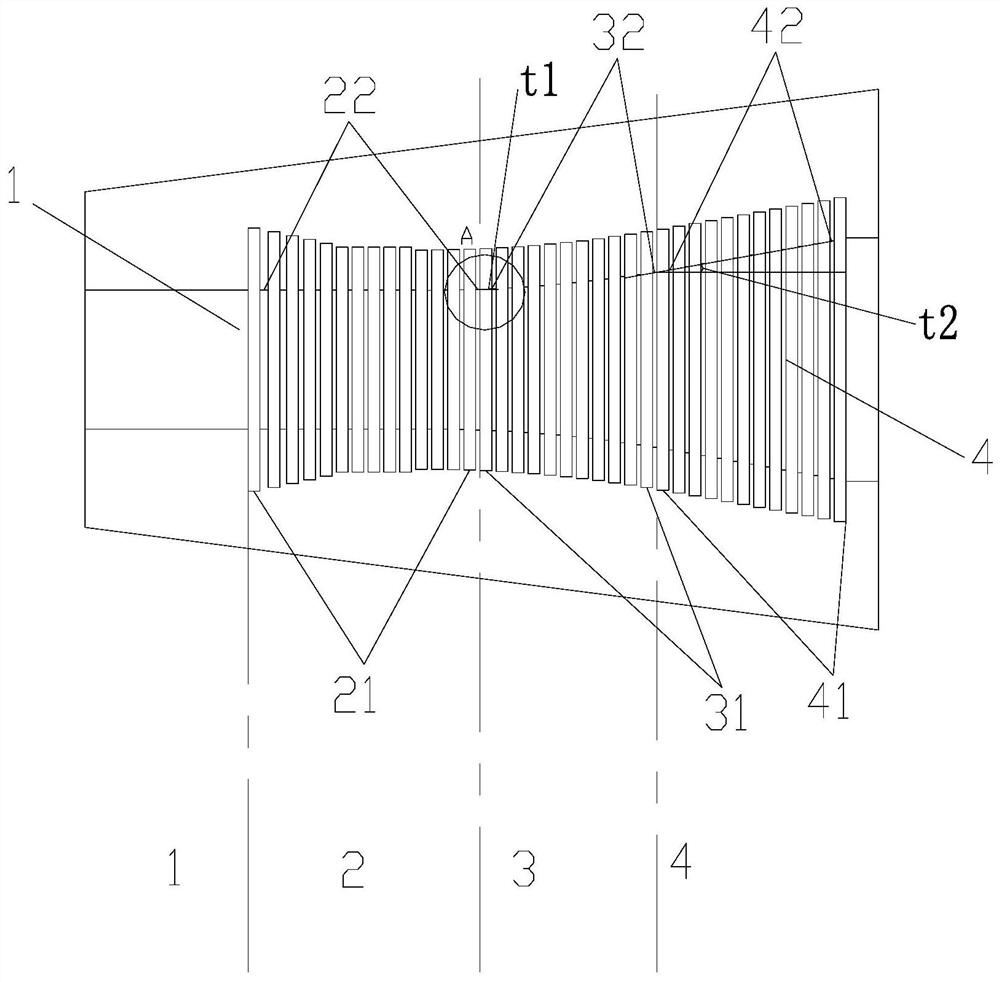
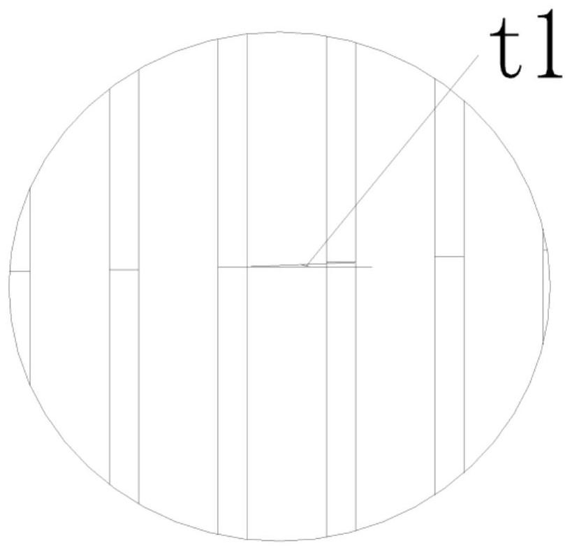
[0027] A millimeter-wave broadband corrugated horn, comprising a circular waveguide 1, a variable mode section 2, a variable angle section 3, and a radiation section 4, the circular waveguide 1 is a first optical wall waveguide, one end is a feed source input end, and the other end is connected to a transformer The inner wall of the mold section 2; the variable mode section 2 is composed of a second light wall waveguide 22 having the same diameter as the inner wall of the circular waveguide 1 and a periodic corrugated structure with gradual changes of several second corrugated grooves 21; the variable angle section 3 is composed of a linear tension The third optical wall waveguide 32 opened and several periodic third corrugated grooves 31 are formed, and the radiation section 4 is composed of a linearly expanded fourth optical wall waveguide 42 and several periodic fourth corrugated grooves 41 structures.

[0028] In the variable mode section 2 from the side close to the circul...

Embodiment 2

[0033] In order to manufacture the millimeter-wave broadband corrugated speaker of Example 1, the method disclosed in this example is to process the circular waveguide 1, the variable mode section 2, the variable angle section 3, and the radiation section 4 in sections, then tooling splicing, and finally welding as a whole .


PUM


Abstract

The invention relates to the technical field of antennas, in particular to a millimeter wave broadband corrugated horn and a manufacturing method thereof. The millimeter wave broadband corrugated horncomprises a circular waveguide, a variable-mode section, a variable-angle section and a radiation section. The circular waveguide is a first optical wall waveguide, one end of the circular waveguideis a feed source input end, and the other end of the circular waveguide is connected with the inner wall of the variable-mode section. The variable mode section is composed of a second optical wall waveguide and a plurality of periodic ripple structures with gradually changed second ripple grooves. The variable-angle section is composed of a third light wall waveguide which is linearly opened anda plurality of periodic third corrugated groove structures, the radiation section is composed of a fourth light wall waveguide which is linearly opened and a plurality of periodic fourth corrugated groove structures, and the diameter of the inner wall of the variable-mode section is the same as that of the inner wall of the circular waveguide. According to the millimeter wave broadband corrugatedhorn provided by the invention, the transition section with the most common groove depth change is adopted to realize the transition from the optical wall waveguide to the corrugated waveguide.

Description

technical field [0001] The invention relates to the technical field of antennas, in particular to a millimeter-wave broadband corrugated horn and a manufacturing method thereof. Background technique [0002] The millimeter-wave corrugated horn has the advantages of wide bandwidth, good directional pattern, and high cross-polarization. It is widely used in radar systems and wireless communication systems. Its main function is as a feed source for reflector antennas, so the performance of the horn directly affects The performance of the whole machine. [0003] In the millimeter wave frequency band, the corrugated speaker with broadband matching is realized, and the main mode of the circular waveguide is TE 11 Modulo conversion to HE 11 The variable mode section of the mold mostly adopts the structure of the ring loading groove. The processing difficulty of the ring loading groove in the millimeter wave frequency band is relatively high, and the processing technology is compl...

Claims


Application Information

Patent Timeline
Patent Type & Authority Applications(China)
IPC IPC(8): H01Q1/36H01Q13/02
CPCH01Q1/36H01Q13/0208H01Q13/0291
Inventor 金秀梅胡卫东李运志
Owner ANHUI SUN CREATE ELECTRONICS
Learn More