Eureka AIR delivers breakthrough ideas for toughest innovation challenges, trusted by R&D personnel around the world.

Dust cleaning device for filtering net of power equipment

A technology for power equipment and cleaning devices, which is applied to the cooling/ventilation of circuit devices, substation/power distribution device shells, substations/switching devices, etc., which can solve the problems of heavy dust particles and reduce the cleaning quality and occupancy Space, reduce the effect of work intensity

Pending Publication Date: 2018-02-09
国网浙江乐清市供电有限公司 +3
View PDF0 Cites 1 Cited by
  • Summary
  • Abstract
  • Description
  • Claims
  • Application Information

AI Technical Summary

Problems solved by technology

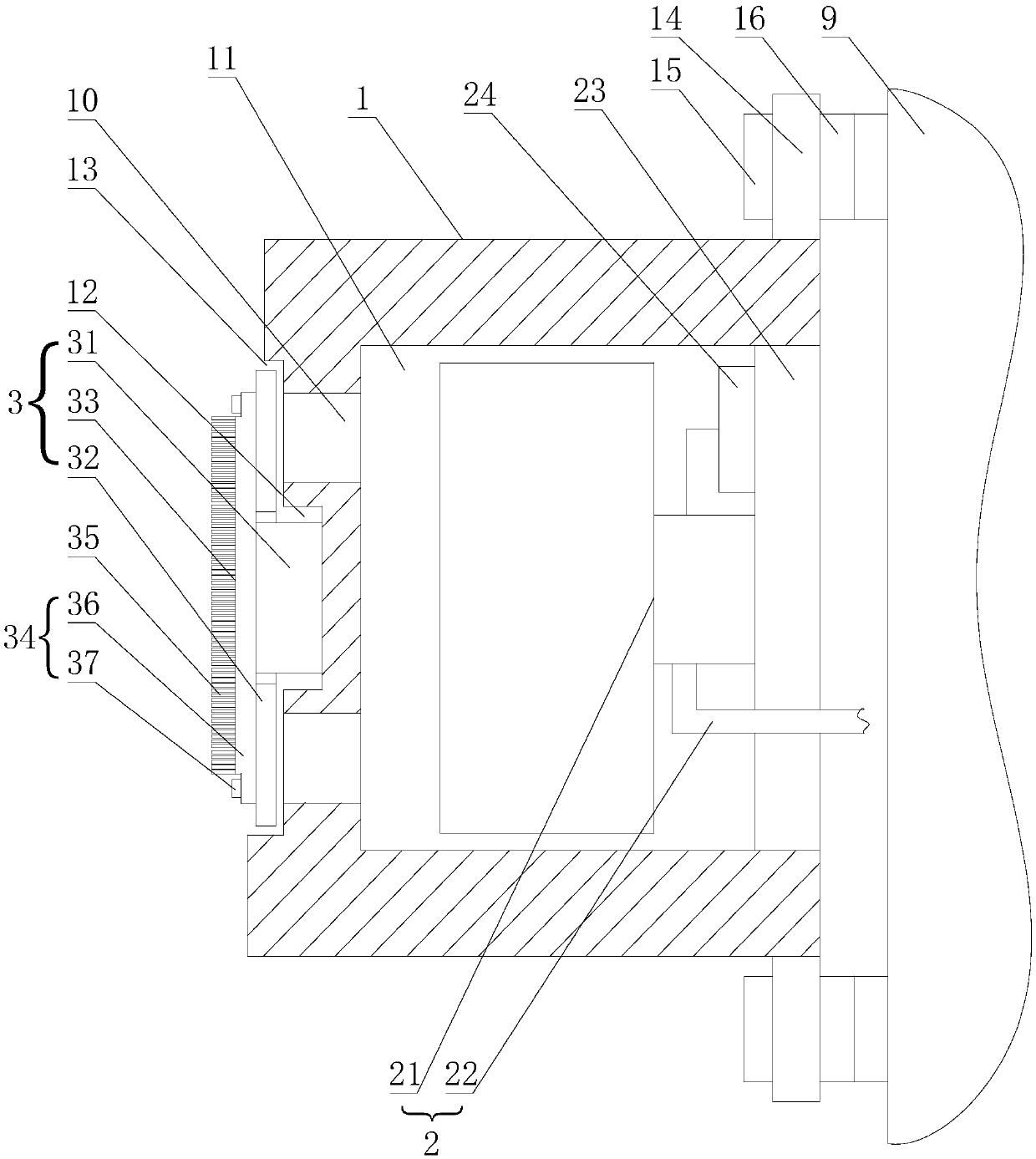
[0003] The technical problem to be solved by the present invention is to provide a dust removal device for the filter screen of electric equipment, and solve the technical problem that the existing manual cleaning of dust particles on the filter screen has a large workload

Method used


Image

  • Dust cleaning device for filtering net of power equipment
  • Dust cleaning device for filtering net of power equipment

Examples


Embodiment 1

[0022] Such as figure 1 As shown, the filter dust removal device of power equipment includes a base 1, a driving mechanism 2 and a cleaning brush 3. The base 1 is provided with a first mounting portion 11 and a second mounting portion 12, and the driving mechanism 2 The cleaning brush 3 is installed on the base 1 through the first installation part 11, and the cleaning brush 3 is installed on the base 1 through the second installation part 12, so that the entire filter dust removal device is formed as a whole, reducing the entire filter dust removal device The installation takes up space, and the overall structure is compact, and the assembly is simple. The cleaning brush 3 relies on the driving force of the driving mechanism 2 to automatically clean the dust on the filter, which can ensure that the filter is not blocked and can reduce the existing manual cleaning work Intensity and cleaning quality, it can effectively solve the problem of anti-clogging of the filter, ensure the...

Embodiment 2

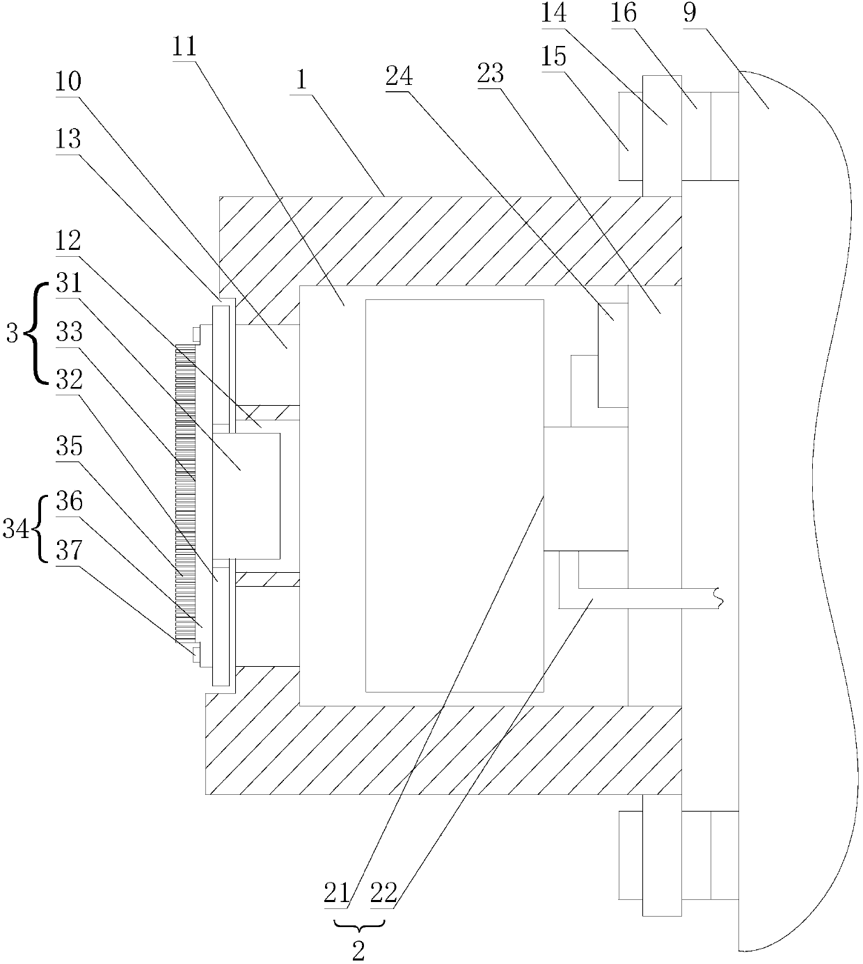
[0027] Like the filter dust removal device of power equipment described in the first embodiment, this embodiment has the following differences: figure 2 As shown, the connecting hole communicates with the cavity, and the rotating shaft is arranged in the cavity. When in use, the wind generated by the fan 21 flows to the cleaning brush 3 through the connecting hole and the ventilation hole 10 to realize the synchronous rotation of the rotating shaft 31 and the blade 32, and further The cleaning effect of the brush 33 is improved.

[0028] The power equipment in this embodiment refers to the GIS control cabinet of an unattended substation. When the GIS control cabinet is in use, dust particles will block the filter. If it is not cleaned in time, it will inevitably affect heat dissipation and lead to signal collection and communication. The malfunction of control and protection functions may endanger the safety of the power grid and cause accidents. The dust remover in this embodim...


PUM


Abstract

The invention relates to a dust cleaning device for a filtering net of power equipment. The dust cleaning device comprises a base, a driving mechanism and a cleaning brush, wherein a first installation part and a second installation part are arranged on the base, the driving mechanism is arranged on the base via the first installation part, the cleaning brush is arranged on the base via the secondinstallation part and is used for automatically cleaning dust on the filtering net by a driving force of the driving mechanism, and the driving mechanism and the cleaning brush are arranged on a power equipment box body with the base. The dust cleaning device has the advantages that the cleaning brush is used for automatically cleaning the dust on the filtering net by the driving force of the driving mechanism, the filtering net can be enabled not to be plugged, the working intensity and the cleaning quality of existing manual cleaning can be reduced, the problem that the filtering net is plugged can be effectively reduced, a smooth heat dissipation passage is guaranteed, a fault is prevented, and the dust cleaning device has social benefit, also has economic value and can be used in thepower equipment in unmanned operation of a power grid.

Description

Technical field [0001] The invention relates to a filter dust removal device for power equipment. Background technique [0002] Existing electric and electronic box equipment, in order to take away the heat generated by the operating equipment in time and ensure the normal operation of the equipment, the hot air in the box is generally pulled out by ventilation to achieve the effect of heat dissipation and cooling, so the box is often There are air inlets and air outlets, and a filter is set on the air inlet to prevent the inhalation of larger dust particles. The dust particles on the filter will accumulate more and more. Manual cleaning is required on schedule to keep the filter from being blocked. , To meet ventilation and heat dissipation, to ensure the normal operation of power and electronic equipment, otherwise it may affect heat dissipation and cause accidents. Summary of the invention [0003] The technical problem to be solved by the present invention is to provide a fil...

Claims


Application Information

Patent Timeline
Patent Type & Authority Applications(China)
IPC IPC(8): H02B1/46H02B1/28H02B1/56H02J9/06
CPCH02B1/28H02B1/46H02B1/565H02J9/06
Inventor 朱海陈浩章雷吴信文肖郭璇
Owner 国网浙江乐清市供电有限公司
Why Eureka
Eureka Blog
Learn More