Half-bridge resonant wireless energy transmission system

A wireless energy transmission and wireless energy transmission technology, applied in electrical components, circuit devices, etc., can solve the problems of destroying the establishment of energy channels, the time-varying uncontrollable range of transmission distance, and the reduction of energy transmission capacity, and achieve the realization of electric energy transmission, high The effect of efficient power transfer

Active Publication Date: 2018-02-09
厦门金固美能源科技有限公司
View PDF6 Cites 4 Cited by
  • Summary
  • Abstract
  • Description
  • Claims
  • Application Information

AI Technical Summary

Problems solved by technology

The maintenance of the resonance state between the energy transmitting end and the receiving end will lead to a time-varying uncontrollable range with the transmission envir

Method used


Image

  • Half-bridge resonant wireless energy transmission system
  • Half-bridge resonant wireless energy transmission system
  • Half-bridge resonant wireless energy transmission system

Examples


Embodiment Construction

[0040] The following embodiments will further illustrate the present invention in conjunction with the accompanying drawings.

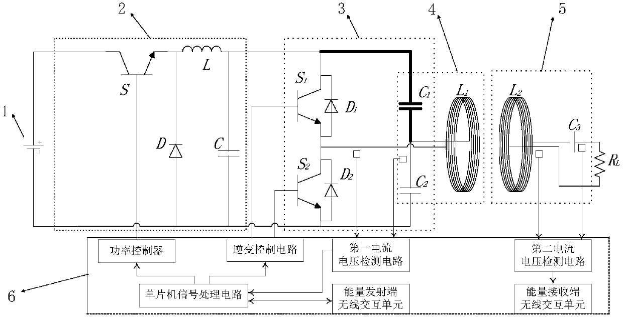
[0041] Such as figure 1 As shown, the embodiment of the present invention includes: a DC power supply 1 , a BUCK circuit 2 , a half-bridge inverter circuit 3 , a first resonator 4 , a second resonator 5 and an auxiliary circuit 6 .

[0042] The output terminal of the DC power supply 1 is connected to the BUCK circuit 2, and the adjustable DC voltage U obtained by chopping the BUCK circuit 2 in As a bus power supply, it is connected to the half-bridge inverter circuit 3; the half-bridge inverter circuit 3 is connected to the first resonator 4; the second resonator 5 induces the magnetic field energy of the first resonator 4, and converts the magnetic field energy into electric energy as a power supply for the load R L powered by;

[0043]The DC power supply 1 part can be, but not limited to, a 314V DC power supply to provide electric energy input. ...


PUM


Abstract

The invention discloses a half-bridge resonant wireless energy transmission system and relates to wireless energy transmission. The half-bridge resonant wireless energy transmission system is providedwith a DC power supply, a BUCK circuit, a half-bridge inverter circuit, a first resonator, a second resonator and an auxiliary circuit. A control method comprises the following steps of achieving adjustment of output power and achieving maintenance of resonant states of the system. Wireless transmission of electric energy is carried out through an inductive coupling mode; maintenance of the resonant states of the system under different power conditions is achieved through adding the BUCK circuit to a preceding stage of the half-bridge inverter circuit; and high-efficiency electric energy transmission is achieved.

Description

technical field [0001] The present invention relates to wireless energy transmission, in particular to a half-bridge resonant wireless energy transmission system. Background technique [0002] Wireless energy transfer is a technology that transfers electrical energy to corresponding devices in a non-physical connection. There are mainly four basic methods: one is the electromagnetic induction coupling method of the loosely coupled transformer model; the other is the magnetic resonance method; the third is the laser and microwave radiation method; the fourth is the electric field coupling method. Among them, the wireless power transmission of the electromagnetic induction coupling method regards the energy transmitting end as the primary of the transformer, and the energy receiving end as the secondary of the transformer, and uses the magnetic coupling method for wireless energy transmission, which is suitable for short-distance (centimeter-level) transmission. Has entered t...

Claims


Application Information

Patent Timeline
IPC IPC(8): H02J50/12
CPCH02J50/12
Inventor 陈文芗洪剑锋赵婉莹易志坤曹福青
Owner 厦门金固美能源科技有限公司
Why Eureka
Try Eureka