Oscillator circuit

An oscillator and circuit technology, applied in electrical components, generating electric pulses, pulse technology, etc., can solve the problems of reducing the stability of circuit oscillation frequency, difficulty in oscillation frequency, process error, etc., and achieve the elimination of transmission delay and stability of oscillation frequency Good results

Active Publication Date: 2018-02-09
SHENZHEN UNIV
View PDF10 Cites 13 Cited by
  • Summary
  • Abstract
  • Description
  • Claims
  • Application Information

AI Technical Summary

Problems solved by technology

However, this design does not eliminate the influence of the offset voltage on the comparator on the reference voltage, so the oscillation frequency generated by this circuit is difficult to achieve high temperature stability
In addition, because this design needs to design a mirror circuit that is well matched with the oscillation circuit to control the charging and discharging speed of the charging and discharging circuit to the capacitor within the transmission delay td, but this design uses too many capacitors and comparators, Therefore, in the actual semiconductor production process, due to some process errors, it is difficult to achieve the required matching degree, so the stability of the oscillation frequency of the circuit is further reduced.

Method used


Image

  • Oscillator circuit
  • Oscillator circuit
  • Oscillator circuit

Examples


Embodiment Construction

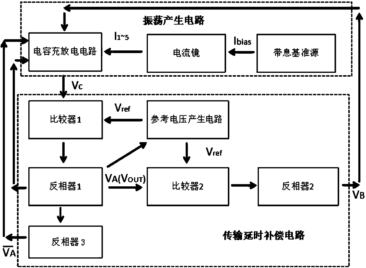
[0018] Such as figure 1 As shown, the oscillator circuit of the embodiment of the present invention is composed of an oscillation generation circuit, a transmission delay compensation circuit and a reference voltage generation circuit.

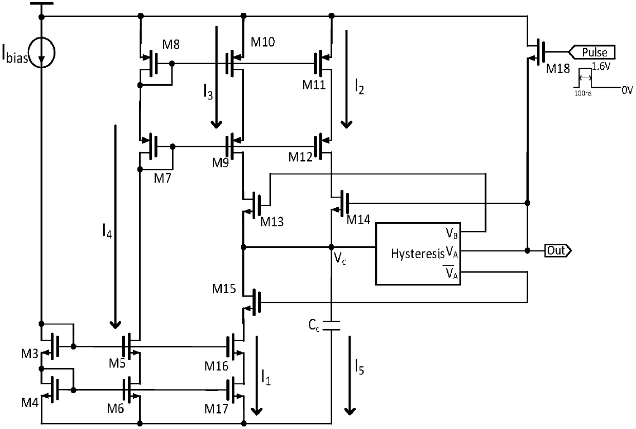
[0019] Such as image 3 As shown, the oscillation generating circuit includes a capacitor C C , capacitor charging and discharging circuit, current mirror circuit and bandgap reference source I BIAS .

[0020] The capacitor charging and discharging circuit includes a first control switch M 13 , the second control switch M 15 and the third control switch M 14 and the excitation switch M 18 .

[0021] The current mirror circuit includes two mirror current sources, and each mirror current source includes an input branch and two output branches.

[0022] The first mirror current source includes 6 NMOS transistors M 3 , M 4 , M 5 , M 6 , M 7 and M 8 , is an NMOS type cascode current mirror. NMOS tube M 3 and M 4 Form the input bran...


PUM


Abstract

The invention discloses an oscillator circuit. The oscillator circuit comprises an oscillation generation circuit, a transmission delay compensation circuit and a reference voltage generation circuit;the oscillation generation circuit comprises a capacitor, a capacitor charge and discharge circuit, a current mirror circuit and a band-gap reference source; and the reference voltage generation circuit generates a high reference voltage and a low reference voltage and controls the oscillation frequency of the oscillation generation circuit through a difference of the two reference voltages. According to the oscillator circuit, the influences of offset voltages of comparators on the frequency are eliminated by means of the mode of controlling the oscillation frequency generated by the chargeand discharge capacitor through the difference of the two reference voltages; and transmission delay is eliminated by the transmission delay compensation circuit, therefore, the stability of the generated frequency can be kept, the area of a needed chip is small, and the power consumption is low.

Description

[technical field] [0001] The present invention relates to an oscillator, in particular to an oscillator circuit. [Background technique] [0002] Document "A 120nW 18.5kHz RC oscillator with comparator offsetcancellation for ±0.25% temperature stability", (http: / / ieeexplore.ieee.org / document / 6487692 / ), through a reference voltage generation circuit and two independent charge and discharge capacitors A reference voltage with a fixed value is proposed to control the charging and discharging time of the charging and discharging capacitor on the comparator to generate an oscillator. It can make the reference voltage alternate at the positive and negative input terminals of the comparator every half cycle, that is, in the first half cycle of an oscillation, the reference voltage is input from the positive phase terminal of the comparator, and the voltage on the capacitor is from the negative phase terminal. Input; the reference voltage of the second half cycle is input from the n...

Claims


Application Information

Patent Timeline
Patent Type & Authority Applications(China)
IPC IPC(8): H03K3/011H03K3/0231
CPCH03K3/011H03K3/0231
Inventor 赵晓锦彭亮多胡德烁温志煌
Owner SHENZHEN UNIV
Why Eureka
Try Eureka