Unlock instant, AI-driven research and patent intelligence for your innovation.

Feed additive mixing equipment

A feed additive and mixing equipment technology, which is applied in mixers, mixers with rotary stirring devices, dissolving and other directions, can solve the problems of low mixing efficiency, uneven mixing, and single mixing direction, and achieve good mixing effect and mixing efficiency. High, improve the effect of stirring speed

Inactive Publication Date: 2018-02-16
广州雅隆自动化设备有限公司
View PDF4 Cites 0 Cited by
  • Summary
  • Abstract
  • Description
  • Claims
  • Application Information

AI Technical Summary

Problems solved by technology

[0002] With the improvement of people's living standards, people's demand for meat continues to increase. However, with the continuous urbanization of rural areas, the number of livestock raised by farmers continues to decrease, while large-scale breeding factories and farms continue to increase. Now meat is basically Generally, it is provided through farm breeding to meet people's demand for meat. In the field of animal husbandry, livestock and poultry are generally fed with feed, but the nutrients that livestock and poultry need to ingest at different growth stages are different. The same, therefore, different additives will be added in different growth stages. Feed and additives need to be stirred evenly before they can be used to benefit the growth of livestock and poultry. In some large-scale breeding plants, pellet feed and Additives are mixed, but the traditional mixing equipment generally stirs the pellet feed and additives through the stirring paddle. This kind of mixing equipment has a single stirring direction, so it will cause the problem of uneven stirring, and the stirring efficiency is low.

Method used


Image

  • Feed additive mixing equipment
  • Feed additive mixing equipment
  • Feed additive mixing equipment

Examples


Embodiment Construction

[0018] All features disclosed in this specification, or steps in all methods or processes disclosed, may be combined in any manner, except for mutually exclusive features and / or steps.

[0019] Any feature disclosed in this specification (including any appended claims, abstract and drawings), unless expressly stated otherwise, may be replaced by alternative features which are equivalent or serve a similar purpose. That is, unless expressly stated otherwise, each feature is one example only of a series of equivalent or similar features.

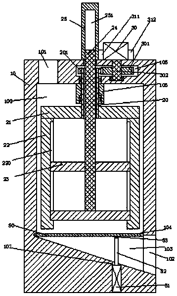
[0020] Such as Figure 1-3 As shown, a feed additive mixing device of the present invention includes a mixing cylinder 10, a mixing chamber 100 is provided in the mixing cylinder 10, and an inlet communicating with the mixing chamber 100 is provided in the top wall of the mixing cylinder 10. A chute 101, a chute 103 is arranged in the bottom wall of the mixing chamber 100, and a turning plate 50 is rotatably installed on the upper end of the ...


PUM


Abstract

The invention relates to feed additive mixing equipment, which comprises a mixing drum, wherein a mixing chamber is arranged in the mixing drum, a material inlet groove communicated to the mixing chamber is arranged in the top wall of the mixing drum, an chute is arranged in the bottom wall of the mixing chamber, the upper end of the chute is rotatably provided with a flipping plate through a pinshaft, a drive assembly for driving the flipping plate to rotate is arranged in the mixing drum, a rotation groove is arranged in the top wall of the mixing chamber, a rotation shaft is rotatably arranged in the rotation groove, and is fixedly provided with a drive gear, the upper end of the rotation shaft is connected to a rotation motor fixedly arranged at the upper end of the mixing drum in a power manner, the center position of the top wall of the mixing chamber is fixedly provided with a reinforcing bush, a rotation bush is rotatably arranged in the reinforcing bush, the upper end of therotation bush extends into the rotation groove and is fixedly provided with a driven gear engaged with the drive gear, the lower end of the rotation bush is fixedly provided with a connection arm, andlongitudinal stirring arms are symmetrically and fixedly arranged at the lower end of the connection arm in a left-and-right manner. The feed additive mixing equipment of the present invention has advantages of good stirring effect and high stirring efficiency.

Description

technical field [0001] The invention relates to the field of animal husbandry equipment, in particular to a feed additive mixing equipment. Background technique [0002] With the improvement of people's living standards, people's demand for meat continues to increase. However, with the continuous urbanization of rural areas, the number of livestock raised by farmers continues to decrease, while large-scale breeding factories and farms continue to increase. Now meat is basically Generally, it is provided through farm breeding to meet people's demand for meat. In the field of animal husbandry, livestock and poultry are generally fed with feed, but the nutrients that livestock and poultry need to ingest at different growth stages are different. The same, therefore, different additives will be added in different growth stages. Feed and additives need to be stirred evenly before they can be used to benefit the growth of livestock and poultry. In some large breeding plants, pellet...

Claims


Application Information

Patent Timeline
IPC IPC(8): B01F7/16B01F7/32B01F15/02B01F27/96
CPCB01F27/806B01F27/96B01F35/751B01F2101/18
Inventor 韦红生付天龙
Owner 广州雅隆自动化设备有限公司