
Laser cutting method

A technology of laser cutting and cutting trajectory, applied in laser welding equipment, welding equipment, metal processing equipment and other directions, can solve the problems of high laser energy density, affecting the quality and concentration of display panel products

Active Publication Date: 2018-02-16
WUHAN CHINA STAR OPTOELECTRONICS SEMICON DISPLAY TECH CO LTD
View PDF7 Cites 8 Cited by
  • Summary
  • Abstract
  • Description
  • Claims
  • Application Information

AI Technical Summary

Problems solved by technology

However, in the process of laser cutting, due to the high energy density of the laser, a large temperature gradient is generated between the cutting position and its surrounding non-cutting positions, resulting in thermal stress between the cutting position and its nearby positions. In turn, it is easy to produce cracks in the direction of the temperature gradient
Especially for irregular cutting areas such as chamfering and perforation, it is easy to produce irregular deformation and concentration of thermal stress, which makes cracks and other defects more likely to occur, which in turn affects the quality of display panel products

Method used


Image

  • Laser cutting method
  • Laser cutting method
  • Laser cutting method

Examples


Embodiment Construction

[0022] The following will clearly and completely describe the technical solutions in the embodiments of the present invention with reference to the drawings in the embodiments of the present invention. Wherein, the accompanying drawings are only used for exemplary illustration, and represent only schematic diagrams, and should not be understood as limitations on this patent.

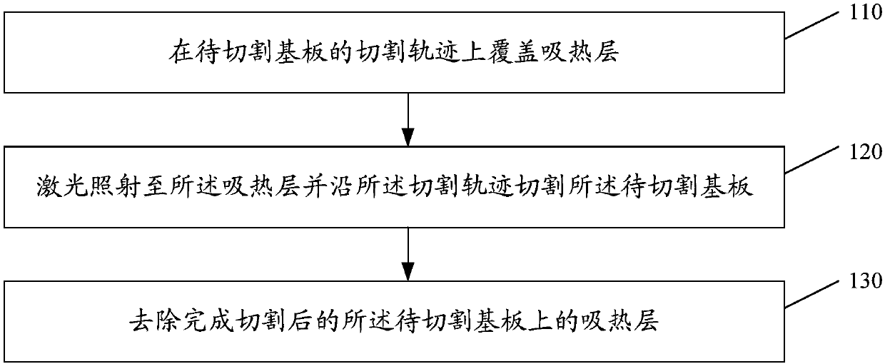
[0023] please participate figure 1 , the present invention provides a kind of laser cutting method, described laser cutting method comprises steps:

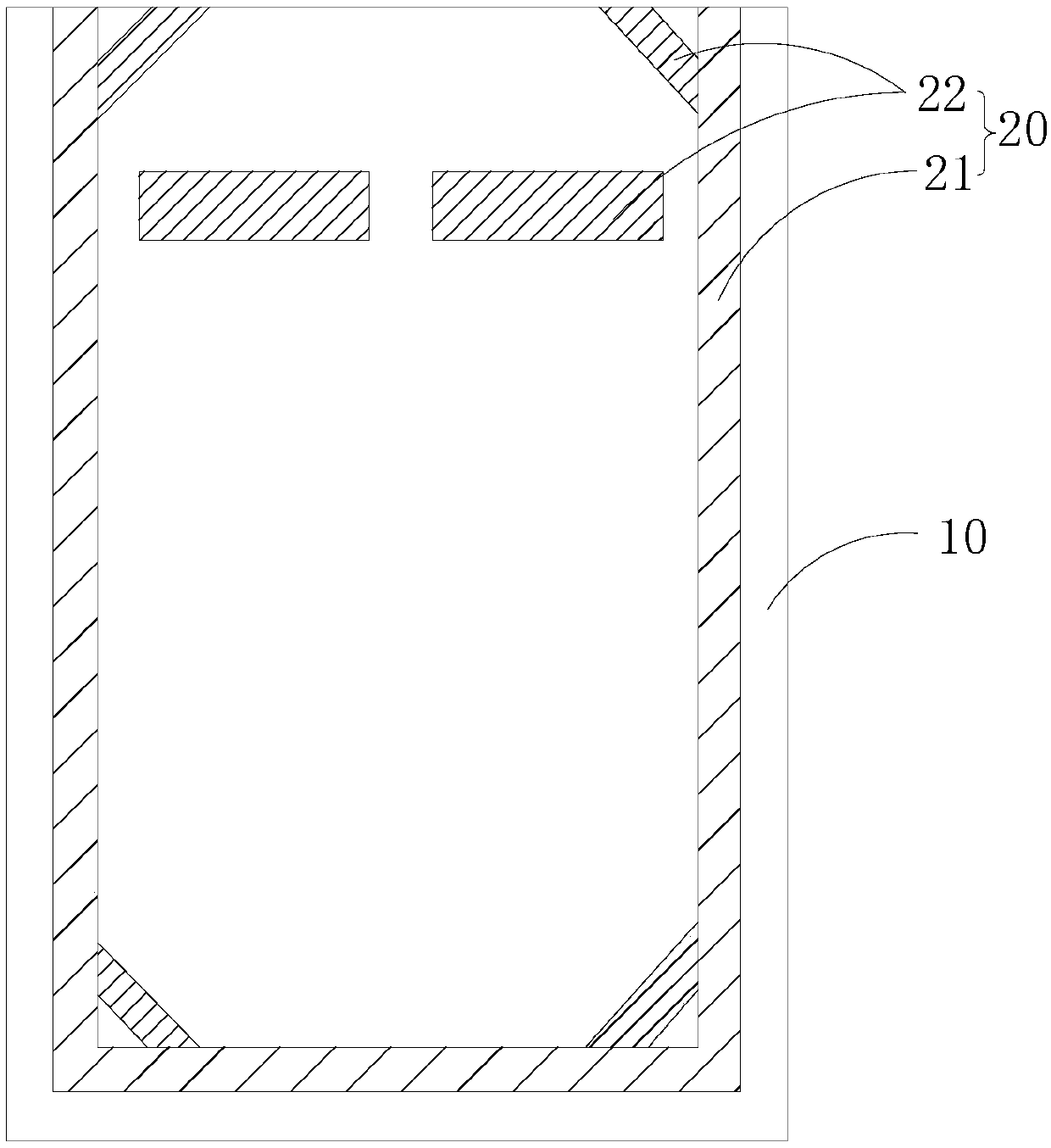
[0024] Step 110, please also refer to figure 2 and image 3 , covering the heat absorbing layer 20 on the cutting track of the substrate 10 to be cut.

[0025] In the present invention, the substrate 10 to be cut is cut by means of laser cutting. The cutting includes cutting the substrate 10 to be cut to obtain a substrate of a suitable size, and also includes chamfering and perforating the substrate 10 to be cut to obtain a substrate with a better app...


PUM


Abstract

The invention provides a laser cutting method. According to the laser cutting method, the cutting track of a to-be-cut substrate is covered with a heat absorbing layer before the laser cutting operation is performed, so that the heat energy of a laser can be partially absorbed by the heat absorbing layer when the to-be-cut substrate is cut by the laser along the cutting track of the to-be-cut substrate; accordingly, the temperature gradient between the cutting position on the to-be-cut substrate and non-cutting positions around the cutting position during the cutting process can be reduced, the heat stress can be reduced, and then cracks and other defects can be reduced; and a relatively-high-quality product can be obtained.

Description

technical field [0001] The invention relates to the technical field of display panel manufacturing, in particular to a laser cutting method. Background technique [0002] In the manufacturing process of the existing display panel, the whole motherboard is usually cut to obtain a display panel with a suitable size. Among them, laser cutting is a commonly used method. However, in the process of laser cutting, due to the high energy density of the laser, a large temperature gradient is generated between the cutting position and its surrounding non-cutting positions, resulting in thermal stress between the cutting position and its nearby positions. Furthermore, it is easy to generate cracks in the direction of pressing the temperature gradient. Especially for irregular cutting areas such as chamfering and perforation, it is easy to generate irregular deformation and concentration of thermal stress, thus more likely to generate defects such as cracks, which further affects the ...

Claims


Application Information

Patent Timeline
IPC IPC(8): B23K26/38B23K26/402
Inventor 袁朝煜
Owner WUHAN CHINA STAR OPTOELECTRONICS SEMICON DISPLAY TECH CO LTD
Learn More