
Plate cutting machine

A cutting machine and plate technology, applied in metal processing and other directions, can solve the problems of workers' health effects, high noise, and dust generation, and achieve the effect of improving cutting efficiency and cutting quality, with low noise and fast completion speed.

Pending Publication Date: 2018-02-16
SUZHOU FUTONG NEW MATERIALS & HIGH TECH
View PDF7 Cites 6 Cited by
  • Summary
  • Abstract
  • Description
  • Claims
  • Application Information

AI Technical Summary

Problems solved by technology

[0004] However, under the limitation of the structure of the circular saw blades of the existing plate cutting machines, the applicable range of the plate thickness of each plate cutting machine is small, and different types of plate cutting machines can only process plates within a certain thickness range , often plates of different thicknesses need to be completed by different types of plate cutting machines
At the same time, the cutting process of the existing plate cutting machine is noisy and produces a lot of dust, which pollutes the working environment and affects the health of the workers.

Method used


Image

  • Plate cutting machine

Examples


Embodiment Construction

[0015] The present invention will be further explained below in conjunction with the accompanying drawings and specific embodiments. It should be understood that the following specific embodiments are only used to illustrate the present invention and are not intended to limit the scope of the present invention. It should be noted that the words "front", "rear", "left", "right", "upper" and "lower" used in the following description refer to the directions in the drawings, and the words "inner" and "outer ” refer to directions towards or away from the geometric center of a particular part, respectively.

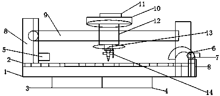
[0016] like figure 1 The plate cutting machine shown includes a worktable 1, a fixed frame, a driving device, a cutting device and a moving device. The bottom of the workbench 1 is provided with a driving device, and the driving device includes a servo motor 3 and a reducer 4. The servo motor 3 The reducer 4 is connected with the moving device respectively. The moving device i...


PUM


Abstract

The invention discloses a plate cutting machine. The plate cutting machine comprises a working table, a fixing frame, a driving device, a cutting device and a moving device, wherein the driving deviceis arranged at the bottom of the working table; the driving device comprises a servo motor and a speed reducer; both the servo motor and the speed reducer are connected with the moving device; the moving device comprises travelling mechanisms arranged on the two sides of the working table separately; a transferring table is arranged on the surface of the working table; compressing devices are arranged on the two sides of the transferring table separately; a locking device is arranged on a moving part; a cutting rod is arranged between the traveling mechanisms; the cutting device is arranged on the cutting rod; a transfer head is arranged at the bottom of a connecting pillar; and a plurality of tool bits are arranged on the transfer head. According to the plate cutting machine, the machineis suitable for a plurality of types of plates, the plates do not need to be adjusted in angles and directions at the same time, the problem that the plates are conveyed to the end for cutting in allangles and directions is solved, the cutting is highly efficient and quick, the working noise is low, the completion speed is high, and the cutting efficiency and quality are effectively improved.

Description

technical field [0001] The invention belongs to the field of cutting machines, in particular to a plate cutting machine. Background technique [0002] The plate cutting machine is a cutting equipment for wood, plastic, color steel and other metal plates. In the prior art, the saw blades of the plate cutting machine are usually circular. During the working process, the circular saw blade is driven by the motor to rotate continuously, and the feeding mechanism continuously drives the plate forward, so that the plate passes through the rotating saw blade. Finish cutting the board. [0003] For example, the existing Chinese invention patent (Patent No. 201010239931.9) discloses an "electric cutting machine" which includes a machine base, a workbench, a motor and a saw blade. In the middle of the table, it is driven by the motor through the pulley and the belt. There is a workpiece conveying platform on the workbench. The workpiece conveying platform is installed in the pulley ...

Claims


Application Information

Patent Timeline
Patent Type & Authority Applications(China)
IPC IPC(8): B26D1/06B26D7/26
CPCB26D1/06B26D7/2614B26D7/2628
Inventor 陈健杨文乾张建光
Owner SUZHOU FUTONG NEW MATERIALS & HIGH TECH
Learn More