Self-unhooking lifting hook

A technology of hooks and lifting lugs, applied in the field of self-decoupling hooks, which can solve problems such as decoupling and increased lifting weight

Inactive Publication Date: 2018-02-16
国网河南省电力公司超高压公司 +1
View PDF9 Cites 3 Cited by
  • Summary
  • Abstract
  • Description
  • Claims
  • Application Information

AI Technical Summary

Problems solved by technology

[0007] In view of this, the object of the present invention is to address the deficiencies of the prior art, to provide a self-decoupling hook, which solves the problem of decoupling in the lifting process by using the counter hook, so that the device is more convenient to operate and safe to use during the lifting process. , while greatly increasing the lifting weight

Method used


Image

  • Self-unhooking lifting hook
  • Self-unhooking lifting hook
  • Self-unhooking lifting hook

Examples


Embodiment 1

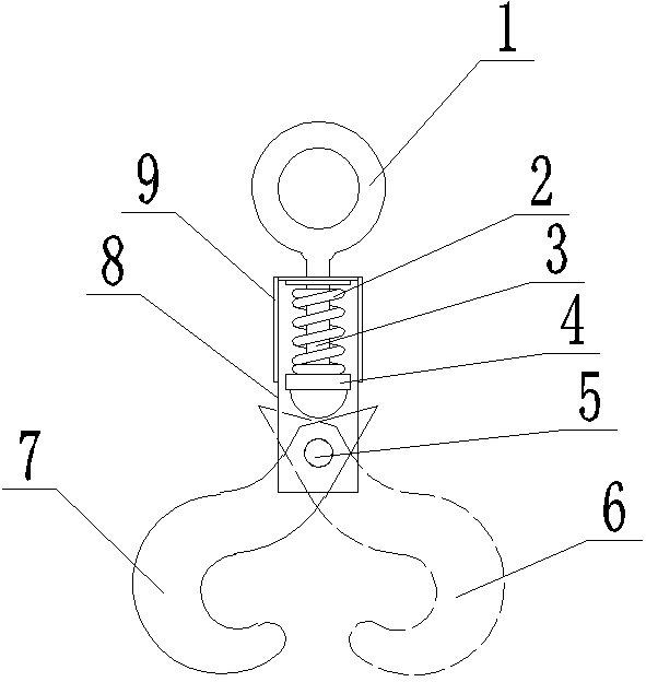
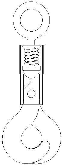
[0026] Such as figure 1 and 2 As shown, a self-decoupling hook includes a left hook 7, a right hook 6, lifting lugs and a frame 8. The frame 8 is made of channel steel with the opening downward, and the bottom and side surfaces of the channel steel are provided with opening; the lug includes a ring 1, a lug handle 3 and a dome nut 4, the lug handle 3 is arranged in the bottom surface hole of the frame 8, and a spring 2 is arranged inside the channel steel of the lug handle 3, so The bottom of the spring 2 is provided with a dome nut 4;

[0027] The spring 2 makes the lifting process more stable, provides a buffer for the moment when the heavy object is stressed, and reduces the unpredictable damage caused by the sudden force on the spreader during the lifting process.

[0028] The upper part of the left hook 7 and the right hook 6 is provided with an inclined surface. When the inclined surface is unloaded, after the lifting lug is not stressed, the dome nut 4 is pushed by th...

Embodiment 2

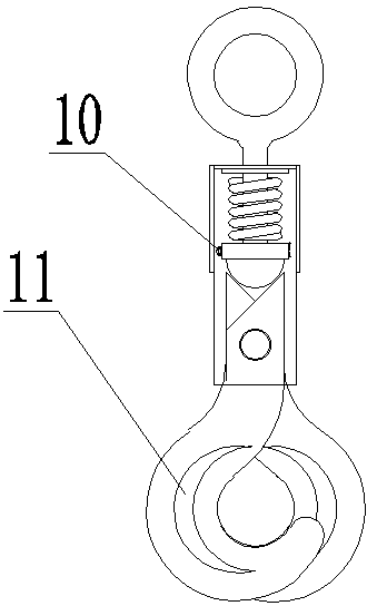
[0033] The main structure of this embodiment is similar to Embodiment 1, and the operation method is the same, and the difference is that: image 3 As shown, the middle part of the dome nut 4 and the lug handle 3 are respectively mainly provided with a through hole, and a cotter pin 10 is arranged in the through hole; by setting the cotter pin 10, the nut can be effectively prevented from loosening, and then the lug and the left Suspension hook 7 and right suspension hook 6 lose connection.

[0034] The hook bodies of the left hook 7 and the right hook 6 are provided with reinforcing ribs 11; through these settings, the overall strength of the hook is further enhanced, and the safety and durability of the entire hook are greatly improved.


PUM


Abstract

The invention discloses a self-unhooking lifting hook. The self-unhooking lifting hook comprises a left lifting hook, a right lifting hook, a lifting lug and a frame; the frame is made of channel steel downwards opened; open holes are formed in the bottom surface and the side surface of the channel steel; the lifting lug comprises a ring, a lifting lug handle and a dome nut; the lifting lug handleis arranged in a hole on the bottom surface of the frame; a spring is arranged on the inner side of channel steel of the lifting lug handle; the dome nut is arranged at the lower part of the spring;inclined surfaces are arranged at the upper parts of the left lifting hook and the right lifting hook; the left lifting hook and the right lifting hook are similar in structure and opposite in direction, and are hinged on the inner side of the channel steel by pin shafts; and pin holes of the left lifting hook and the right lifting hook are formed in the sides, far from hook bodies, of the gravitycenters of the left lifting hook and the right lifting hook. The hook pair is used for solving the unhooking problem in the lifting process, so that the lifting process of the device is more convenient to operate, the use is safe, and meanwhile, the lifting weight is greatly increased.

Description

technical field [0001] The invention relates to the technical field of power failure maintenance of power distribution lines and equipment, in particular to a self-decoupling hook. Background technique [0002] In the installation and maintenance of power equipment, the use of large power equipment and construction tools such as transformers and isolating switches is often involved. Such equipment is often large in size and weight, and it is often necessary to conduct horizontal or Frequent transfer or transportation operations in the vertical direction. In order to overcome this problem, it is often necessary to use traditional transportation vehicles or lifting equipment to realize the transfer or transportation of such equipment in construction. However, the structure of traditional transportation vehicles or lifting equipment It is often large, and it is easy to be restricted by the construction site when used in a small construction area. It is extremely inconvenient to...

Claims


Application Information

Patent Timeline
Patent Type & Authority Applications(China)
IPC IPC(8): B66C1/38
CPCB66C1/38
Inventor 张利王来军张华申晓春
Owner 国网河南省电力公司超高压公司
Why Eureka
Try Eureka