Miniature road tamping device

A tamping device and a technology for roads, which are applied in roads, roads, road repairs, etc., can solve the problems of slow speed, inability to adjust the tamping strength, and increase costs, so as to achieve the effects of improving construction efficiency, improving tamping quality, and reducing costs

Active Publication Date: 2018-02-16
徐州山美环保科技发展有限公司
View PDF5 Cites 7 Cited by
  • Summary
  • Abstract
  • Description
  • Claims
  • Application Information

AI Technical Summary

Problems solved by technology

[0002] At present, when working on small-scale road construction or on roads with relatively soft soil, in order to improve the pressure resistance of the road surface, tamping machines are used. Traditional tamping uses vibratory tamping machines that move manually or large-scale hydraulic tamping. The tamping method is slow, the action area is small, and the energy consumption is relatively large. It is relatively vacant in the field of small-scale compaction equipment in our country. It cannot form an effective and reasonable complement with large-scale equipment, which greatly reduces the efficiency of construction and increases the cost of construction. In addition , the existing tamping device cannot adjust the tamping force according to the actual situation, resulting in poor compaction effect and unguaranteed quality

Method used


Image

  • Miniature road tamping device
  • Miniature road tamping device
  • Miniature road tamping device

Examples


Embodiment Construction

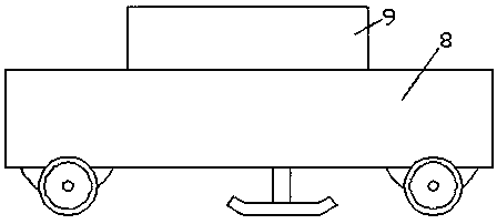
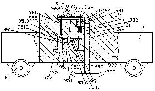
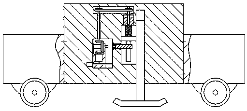
[0014] Such as Figure 1-Figure 4 As shown, a small road compacting device of the present invention includes a loading car body 8 and a tamping body 9 fixedly installed in the loading car body 8. Tamp the first chute 92 on the bottom end surface of the body 9, the left inner wall of the first chute 92 is connected with a transmission groove 93, and the inner top wall of the transmission groove 93 is connected with a guide chute 94, and the guide slide The inner wall of the tamping body 9 on the upper side of the groove 94 is provided with a transmission chamber 96 extending to the left, and the inner wall of the tamping body 9 on the left side of the transmission groove 93 is provided with an adjustment drive chamber 95, and the adjustment drive The top end of the cavity 95 is located directly below the left extension of the transmission groove 93, and the first sliding groove 92 is connected with a rectangular and downwardly extending first sliding rod 921 in a sliding fit. T...


PUM


Abstract

The invention discloses a miniature road tamping device. The miniature road tamping device comprises a load vehicle body and a tamping machine body which is fixedly mounted in the load vehicle body, wherein a first sliding slot which extends downwards and penetrates through the bottom end surface of the tamping machine body is formed in the tamping machine body; a transmission slot is formed in the inner wall of the left side of the first sliding slot in a communicating manner; a slide guiding slot is formed in the top wall in the transmission slot in the communicating manner; a transmission chamber which extends leftwards is formed in the wall body in the tamping machine body, on the upper side of the slide guiding slot; an adjustment driving chamber is formed in the wall body in the tamping machine body, on the left side of the transmission slot; the tail end of the top of the adjustment driving chamber is located right below the left extending segment of the transmission slot; a first siding rod which is rectangular and extends downwards is in sliding fit connection to the first sliding slot; the extending tail end at the bottom of the first sliding rod extends out of the bottomend surface of the tamping machine body; and a tamping head is fixedly arranged at the tail end. The miniature road tamping device disclosed by the invention is simple in structure and convenient tooperate, different tamping work demands can be met, and the tamping quality is improved; and besides, the construction efficiency is greatly improved, and the construction cost is reduced.

Description

technical field [0001] The invention relates to the technical field of road construction machinery, in particular to a small road compacting device. Background technique [0002] At present, when working on small-scale road construction or on roads with relatively soft soil, in order to improve the pressure resistance of the road surface, tamping machines are used. Traditional tamping uses vibratory tamping machines that move manually or large-scale hydraulic tamping. The tamping method is slow, the action area is small, and the energy consumption is relatively large. It is relatively vacant in the field of small-scale compaction equipment in our country. It cannot form an effective and reasonable complement with large-scale equipment, which greatly reduces the efficiency of construction and increases the cost of construction. In addition Therefore, the existing compaction device cannot adjust the compaction intensity according to the actual situation, resulting in poor comp...

Claims


Application Information

Patent Timeline
Patent Type & Authority Applications(China)
IPC IPC(8): E01C19/34
CPCE01C19/34
Inventor 胡小君
Owner 徐州山美环保科技发展有限公司
Why Eureka
Try Eureka