A step-by-step rubber cup packer that can be dragged under pressure and its application method

A leather cup packer and dragging technology under pressure, applied in the directions of sealing/isolation, earthwork drilling, wellbore/well components, etc. The effect of reducing the probability of wear and meeting the requirements of the operation

CN107701145BActive Publication Date: 2019-06-18CNOOC ENERGY TECH & SERVICES
8 Cites 1 Cited by

Patent Information

Authority / Receiving Office
CN · China
Patent Type
Patents(China)
Current Assignee / Owner
Publication Date
2019-06-18

Smart Images

  • Figure 1
    Figure 1
  • Figure 2
    Figure 2
Patent Text Reader

Abstract

The invention discloses a stepping type cup packer capable of achieving dragging under pressure and a using method. The packer comprises a main shaft and a core shaft arranged in the main shaft, a cupseat and a cup directly vulcanized to the cup seat are arranged on the outer diameter of the main shaft, and the rear portion of the cup seat is connected with a pressure relief short section. The rear portion of the pressure relief short section is provided with a seal seat and a rest spring, a sliding sleeve constituting a matching pair with the pressure relief short section is arranged on theouter sides of the seal seat and the reset spring and connected with an elastic claw, and a pressing sleeve connected with the main shaft is mounted on the outer side of the elastic claw. Pressure conducting holes capable of conducting the pressure into the pressing sleeve are formed in the core shaft and the main shaft correspondingly. The using method of the stepping type cup packer has the advantages that the cup can be subjected to coupling through a sleeve pipe under the pressure balance state, the abrasion probability of the cup at the coupling position is effectively reduced, and the sliding sleeve moves downwards to automatically recover to the state that the sliding sleeve and the pressure relief short section are sealed after the cup is subjected to coupling through the sleeve pipe; and through stepping type matching using of the two sets of cup packers, the operation requirement of on-site annulus bearing can be met, an oil sleeve annulus is effectively packed, and the operation danger and the construction cost are reduced.
Need to check novelty before this filing date? Find Prior Art

Description

technical field

[0001] The invention relates to the technical field of oil field development and production, more specifically, the invention relates to a stepping leather cup packer that can be dragged under pressure and a usage method used in oil field development operations. Background technique

[0002] With the development of offshore oil industry, operation timeliness, operation cost and operation safety are becoming more and more the key to operation. In the process of completion and workover operations, the scraper sand washing operation as a basic operation step is the key to ensure the normal operation of subsequent operations. If the appropriate scraper sand flushing technology and tools can be adopted, it can not only improve the operation quality, avoid complex situations in subsequent operations and even avoid downhole accidents, but also improve the operation efficiency of the entire well completion and workover operations. Shorten the operation cycle and red...

Examples

Embodiment Construction

[0028] In order to make the present invention easier to understand, the technical solutions of the present invention will be described in detail below in conjunction with the accompanying drawings and embodiments.

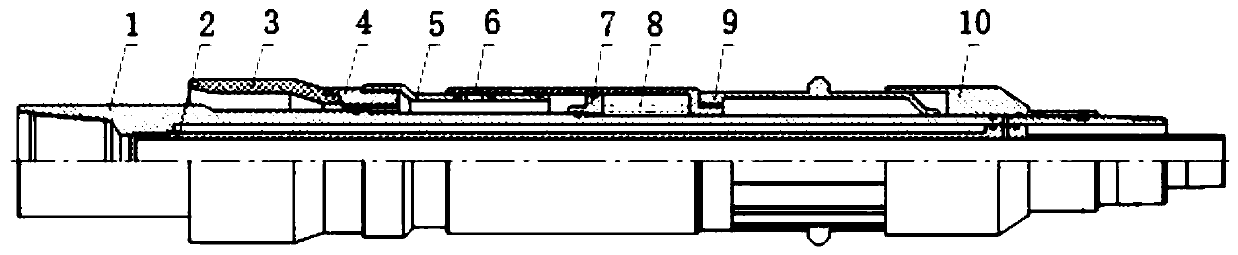
[0029] refer to figure 1 , the pressure-dragging stepping cup packer of the present invention includes a hollow main shaft 1 and a mandrel 2 installed inside the main shaft 1 for pressure transmission, and the outer diameter of the main shaft 1 is threaded The cup seat 4 and the cup 3 directly vulcanized on the cup seat 4, the rear part of the cup seat 4 is connected with the pressure relief nipple 5, and the seal seat 7 is installed at the rear of the pressure relief nipple 5 And the return spring 8, the outer side of the sealing seat 7 and the return spring 8 is equipped with a sliding sleeve 6 sealingly matched with the pressure relief joint 5, the sliding sleeve 6 is connected to the elastic claw 9, and the elastic claw 9 The pressure sleeve 10 connected to th...