
Conversion mechanism for spring pressure gauge

A conversion mechanism and spring pressure technology, which is applied in the measurement of fluid pressure, the measurement of elastic deformation force through the measurement gauge, and the measurement of force, can solve the problems of complex structure of the conversion mechanism, cumbersome assembly operations, and unfavorable assembly efficiency. Small size, convenient assembly and operation, simple and reasonable structure

Pending Publication Date: 2018-02-16
仙居县众鑫仪表制造有限公司
View PDF1 Cites 2 Cited by
  • Summary
  • Abstract
  • Description
  • Claims
  • Application Information

AI Technical Summary

Problems solved by technology

The structure of the conversion mechanism in the pressure gauge disclosed in the above-mentioned patent documents is complex, and the assembly operation is cumbersome, time-consuming and labor-intensive, which is not conducive to improving assembly efficiency

Method used


Image

  • Conversion mechanism for spring pressure gauge
  • Conversion mechanism for spring pressure gauge
  • Conversion mechanism for spring pressure gauge

Examples


Embodiment Construction

[0020] Below in conjunction with accompanying drawing, concrete structure among the present invention is described:

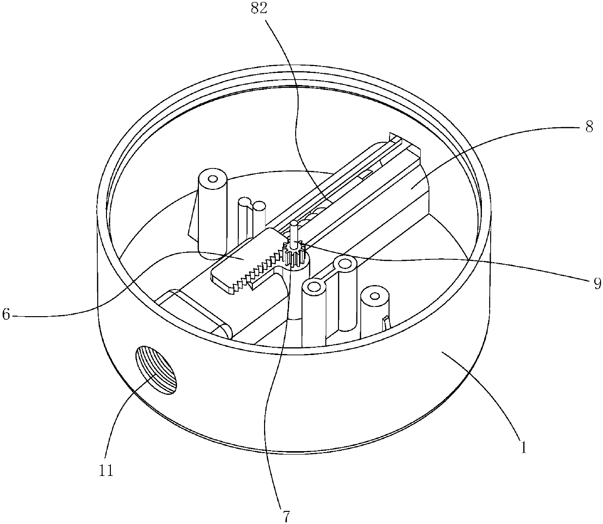
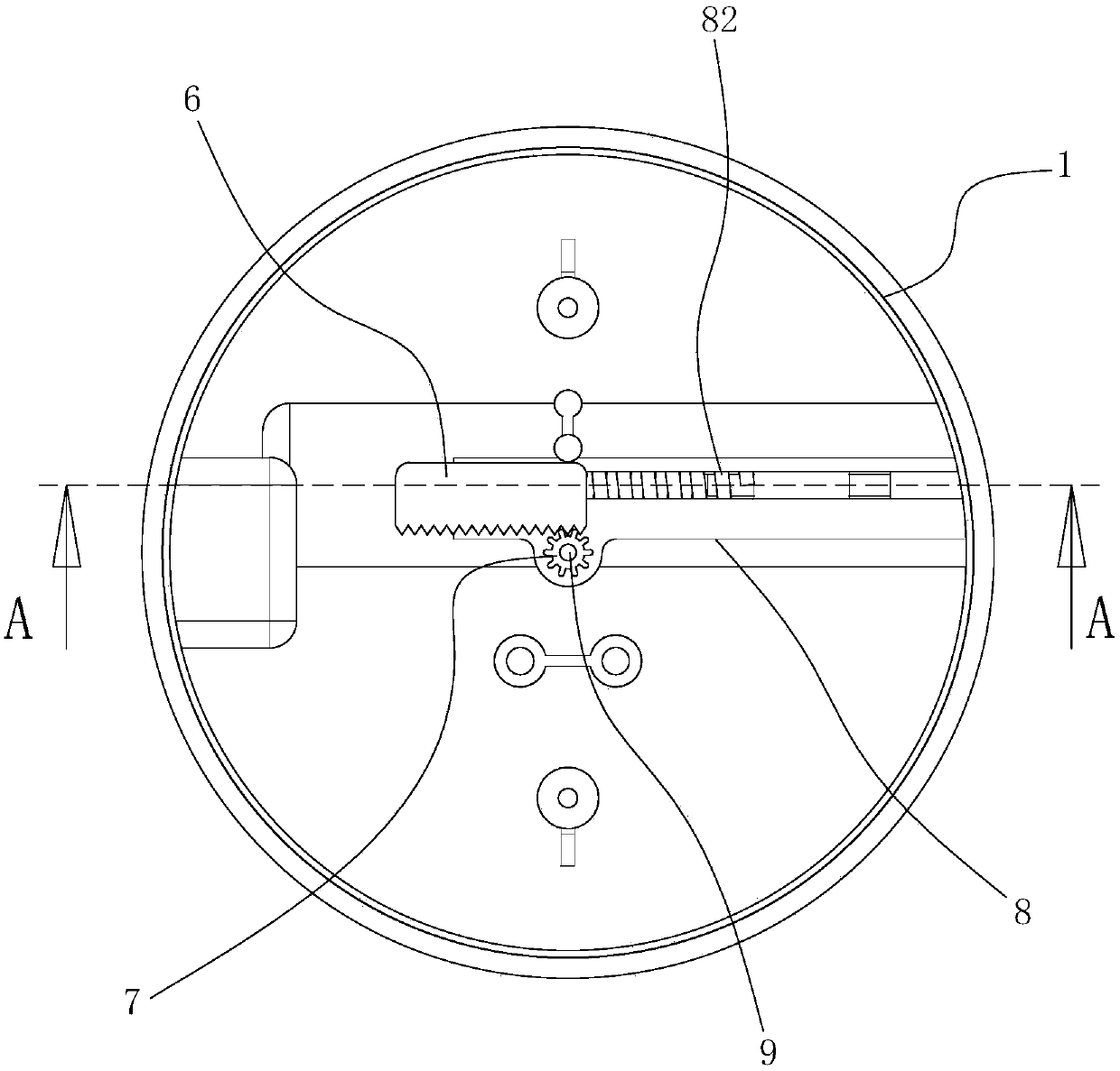
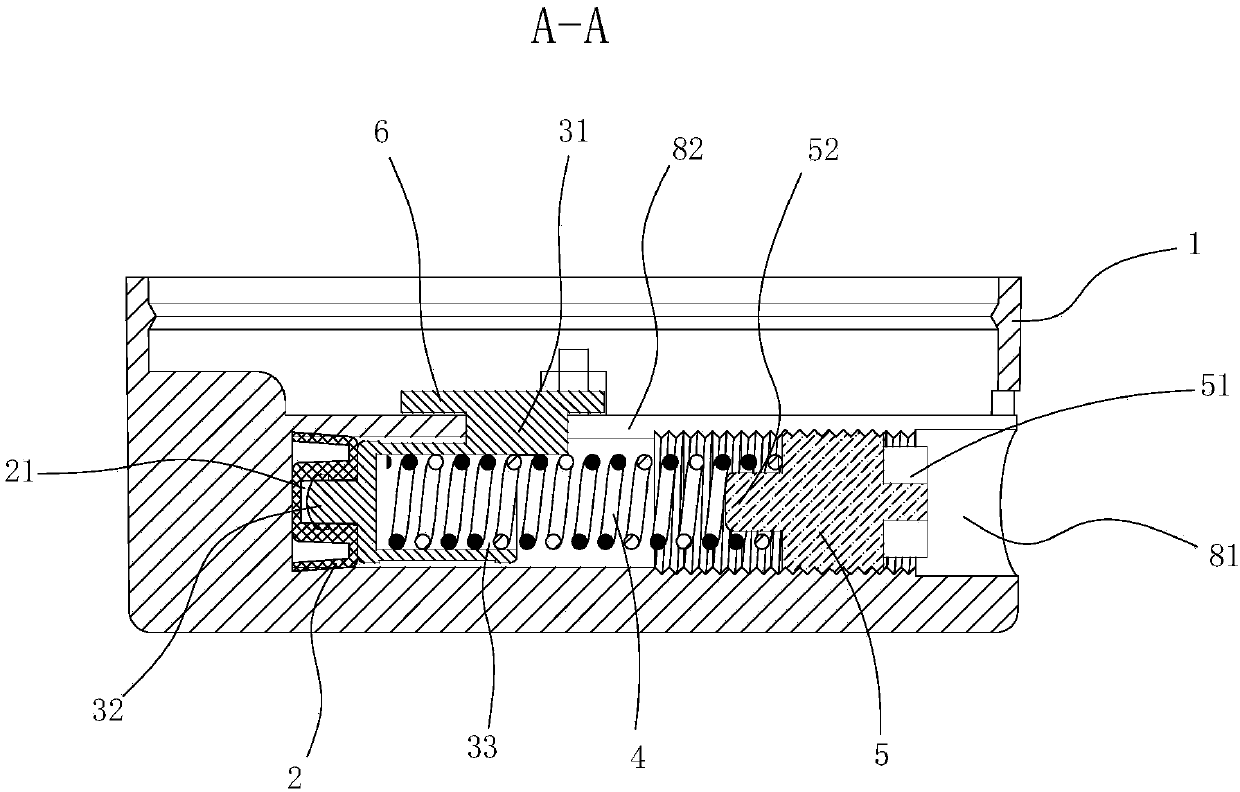
[0021] A conversion mechanism for a spring pressure gauge, such as Figure 1 to Figure 6 As shown, it includes a watch case 1, a seal 2, a piston block 3, a spring 4, a limit member 5, a transmission rack 6 and a transmission gear 7, and the inner bottom of the watch case 1 is integrally formed with a tubular shell arranged horizontally. body 8, an air port 11 is formed on the side wall of the watch case 1, and an air inlet passage 10 connecting the inner cavity of the tubular case 8 and the air port 11 is formed at one end of the tubular case 8 , the other end of the tubular housing 8, that is, the side wall of the watch case 1, is provided with an opening 81, and the sealing member 2, the piston block 3, the spring 4 and the limiting member 5 are formed by The openings 81 are sequentially loaded into the tubular housing 8, the sealing member 2 is fixed on th...


PUM


Abstract

The invention discloses a conversion mechanism for a spring pressure gauge, and the mechanism comprises a case, a sealing part, a piston block, a spring, a limiting part, a drive rack, and a drive gear. The internal bottom of the case is provided with a lateral tubular housing in an integrated manner, and the other end of the tubular housing is provided with an opening. The sealing part, the piston block, the spring and the limiting part are sequentially installed in the tubular housing from the opening. The sealing part is fixed on the piston block, and two ends of the spring respectively abut against the piston block and the limiting part. The limiting part is fixed in the tubular housing, and a side wall of the tubular housing is provided with a strip-shaped hole which axially extends along the tubular housing. The piston block is provided with a connecting block which stretches out of the tubular housing through the strip-shaped hole. The drive rack is movably disposed in the case,and is fixedly connected with the connecting block. The drive gear is coaxially fixed on a pointer installation rotating shaft, and the teeth on the drive gear are engaged with the teeth on the driverack. The mechanism is simple and reasonable in structure, is convenient to assemble and operate, is small in size of products, and is beautiful in shape.

Description

technical field [0001] The invention relates to a conversion mechanism for a spring pressure gauge, which belongs to the field of spring pressure gauge structure design. Background technique [0002] A pressure gauge refers to an instrument that uses elastic elements as sensitive elements to measure and indicate pressure higher than the environment. The pressure gauge uses the elastic deformation of the sensitive element in the gauge, and then transmits the pressure deformation to the pointer by the conversion mechanism, causing the pointer to rotate to display the pressure. Pressure gauges are used in almost all industrial processes and scientific research fields, and can be seen everywhere in heat pipe networks, oil and gas transmission, water and gas supply systems, vehicle maintenance shops and other fields. A spring tube pressure gauge is disclosed in the patent document CN205426390U, which includes a case, the inner wall of the gauge is provided with a sealing gasket,...

Claims


Application Information

Patent Timeline
IPC IPC(8): G01L1/04G01L19/00
CPCG01L1/042G01L19/00
Inventor 徐麒雄赵志武吴国斌
Owner 仙居县众鑫仪表制造有限公司
Features
  • Generate Ideas
  • Intellectual Property
  • Life Sciences
  • Materials
  • Tech Scout
  • Unparalleled Data Quality
  • Higher Quality Content
  • 60% Fewer Hallucinations
Learn More