

A Microscope Hot Stage and Microscopic Melting Point Measuring Apparatus
A technology of microscope and sliding structure, applied in the investigation stage/state change and other directions, can solve the problems of slow heating and cooling speed, inconvenient use of hot stage, bulky heating stage, etc., to achieve fast heating and cooling rate, long service life, high temperature uniform effect
- Summary
- Abstract
- Description
- Claims
- Application Information
AI Technical Summary
Problems solved by technology
Method used
Image

Examples
Embodiment 1
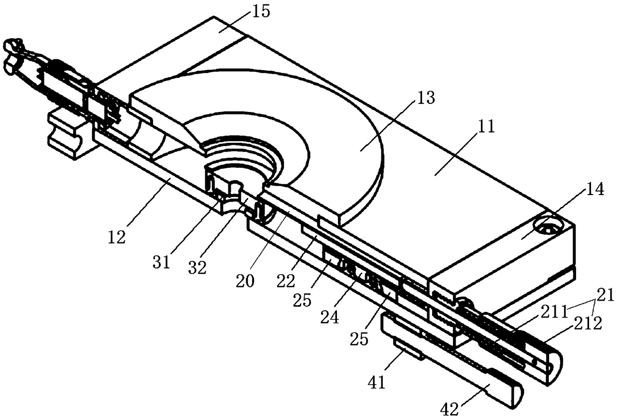
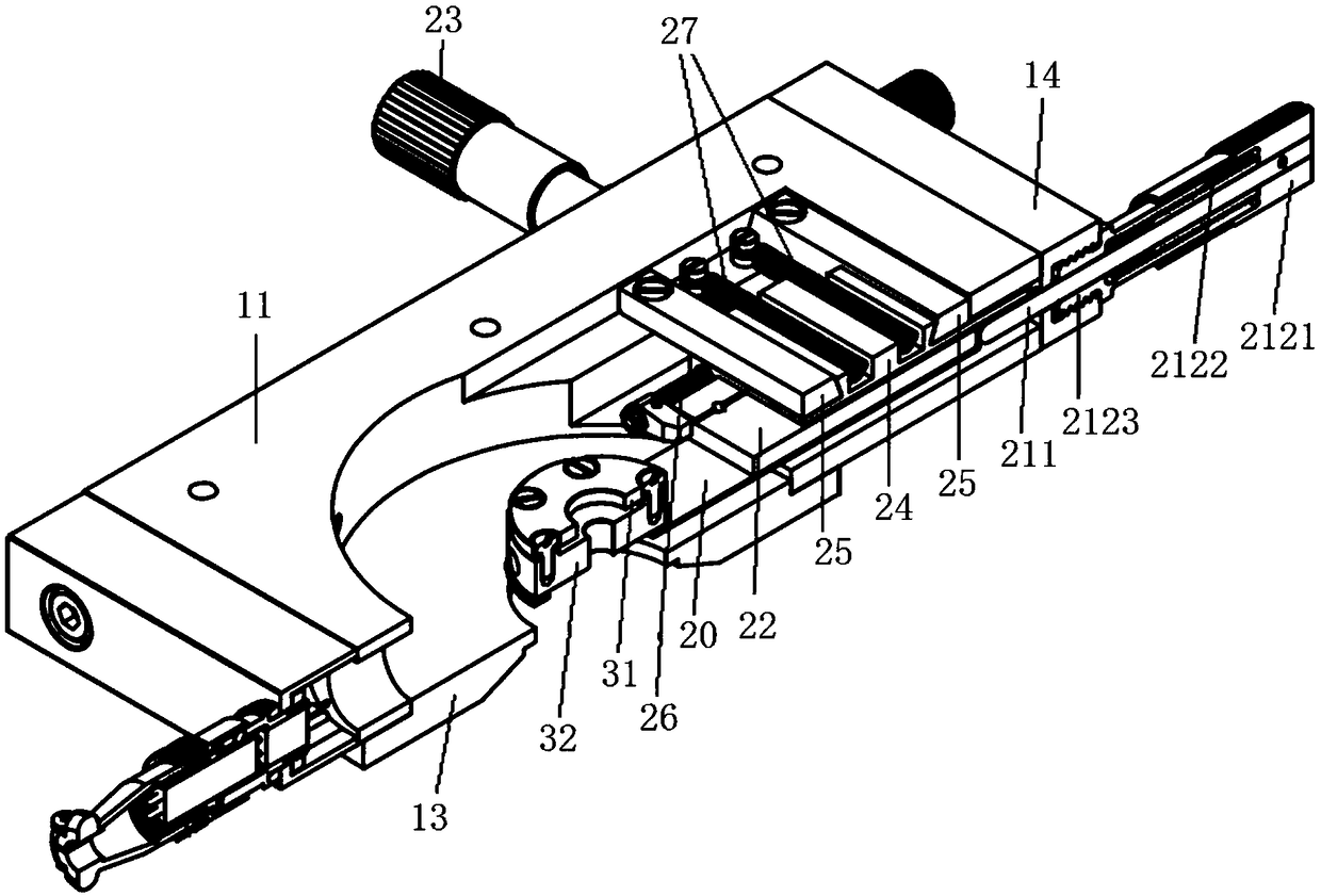
[0063] This embodiment provides a microscope hot stage, specifically, as Figure 1 to Figure 4 As shown, the microscope heating stage in this embodiment includes a casing, a sliding structure 20 and an adjustment device; wherein, the sliding structure 20 is disposed in the casing, and the sliding structure 20 has an accommodating space for accommodating a slide carrying a sample. The adjusting device is used to move the sliding structure 20 along the X-axis and / or the Y-axis (the X-axis and the Y-axis are two directions perpendicular to each other here), so as to adjust the view position of the sample.
[0064] In this embodiment, the Y-axis direction is the axial direction of the sliding structure 20 .
[0065] The microscope heating stage provided in this embodiment is provided with a sliding structure 20 for accommodating the sample slide, and an adjustment device for moving the sliding structure 20 along the X-axis direction and / or the Y-axis direction, so that the microsc...
Embodiment 2
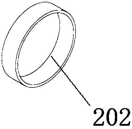
[0067] Preferably, this embodiment provides a microscope hot stage. Compared with the previous embodiment, this embodiment further designs a pair of sliding structures as follows: Figure 1 to Figure 4 As shown, the sliding structure 20 in this embodiment includes a sliding structure main body 201 and an accommodating ring 202 . Wherein, the sliding structure main body 201 is a sheet structure, preferably a metal sheet structure. One end of the sliding structure main body 201 defines a receiving hole 2011 . The accommodating ring 202 is a metal ring structure installed on the accommodating hole 2011, and the accommodating ring 202 is used for accommodating the sample-carrying sheet carrying the sample.
[0068] Preferably, the accommodating hole 2011 is a circular hole; correspondingly, the accommodating ring 202 is a circular ring.
[0069] Preferably, the sample-loading sheet is a glass sheet. Specifically, when accommodating the sample, first place the first glass sheet i...
Embodiment 3
[0071] Preferably, this embodiment provides a microscope hot stage, compared with the above embodiment, such as figure 1 , figure 2 , Figure 4 and Figure 5 As shown, the adjustment device in this embodiment includes a Y-axis adjustment device. Specifically, the Y-axis adjustment device includes: a moving block 22, a first elastic member 26, and a first push rod assembly 21; wherein, the moving block 22 and the sliding structure 20 connections. One end of the first elastic member 26 is fixed on the shell, and the other end is connected with the moving block 22 . The first push rod assembly 21 is threadedly connected with the casing, and one end of the first push rod assembly 21 is located inside the casing, and abuts against the moving block 22 (in contact with force), and the other end is located outside the casing. In this embodiment, through the above configuration, the purpose of controlling the movement of the sliding structure 20 along the Y-axis direction can be a...
PUM
| Property | Measurement | Unit |
|---|---|---|
| thickness | aaaaa | aaaaa |
Abstract
Description
Claims
Application Information