Design method for reducing assembly stress of main shaft and impeller and bending deformation of main shaft

A technology of bending deformation and spindle, which is applied in the fields of manufacturing and assembly, and large-scale mechanical equipment design. It can solve problems such as stress concentration and bending deformation of the spindle, and achieve the effects of reducing the degree of bending deformation, simplifying the manufacturing process, and reducing contact pressure.

Active Publication Date: 2018-02-16
DALIAN UNIV OF TECH +1
View PDF2 Cites 0 Cited by
  • Summary
  • Abstract
  • Description
  • Claims
  • Application Information

AI Technical Summary

Problems solved by technology

[0004] The technical problem to be solved by the present invention is the stress concentration and the bending deformation of the main shaft when the main shaft and the impeller of the large rotating machine are assembled in interference

Method used


Image

  • Design method for reducing assembly stress of main shaft and impeller and bending deformation of main shaft
  • Design method for reducing assembly stress of main shaft and impeller and bending deformation of main shaft
  • Design method for reducing assembly stress of main shaft and impeller and bending deformation of main shaft

Examples


Embodiment 1

[0033] Embodiment 1 Analysis of influence of semicircular groove structure on assembly performance

[0034] A. Set the corresponding thermal boundary conditions and mechanical boundary conditions according to the actual assembly conditions.

[0035] B. Calculate the main shaft bending deformation, Mises stress, contact pressure and friction torque when the groove is not set as a comparative example, and record it in Table 2.

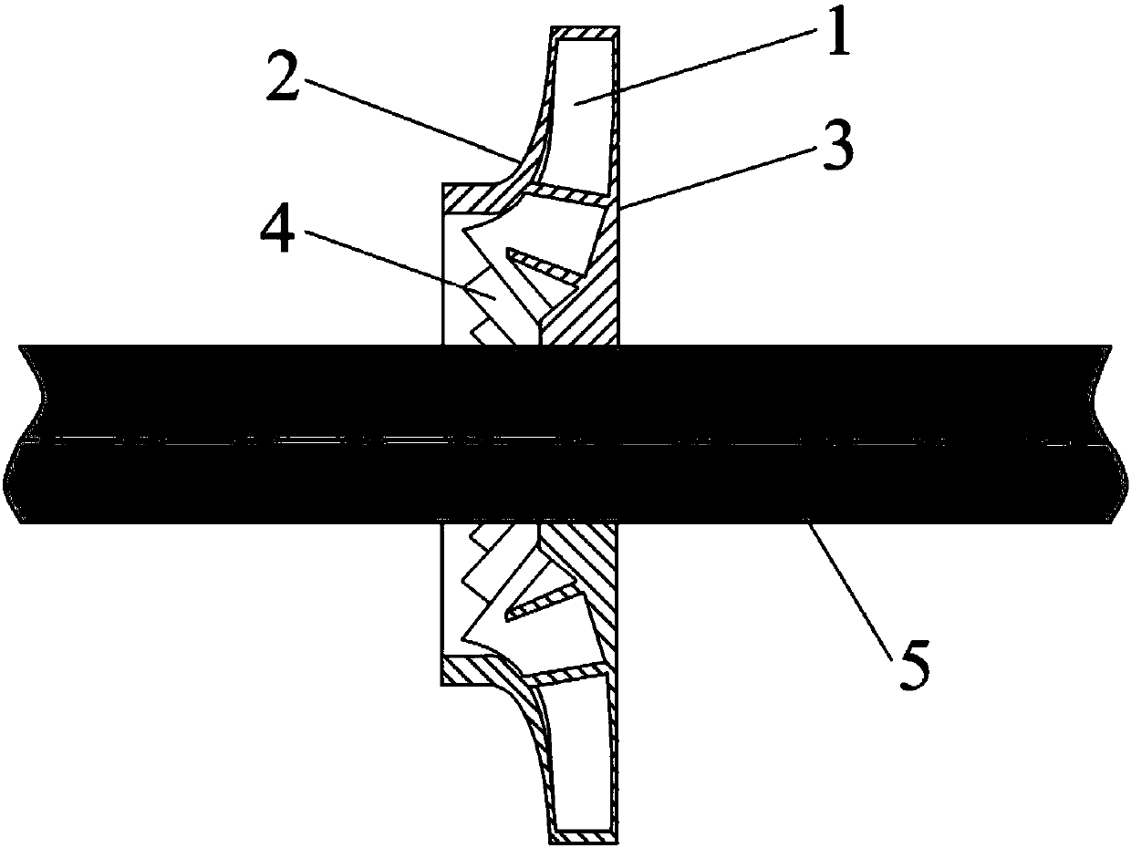
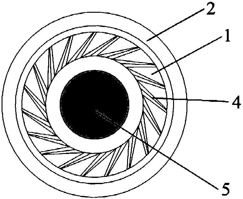
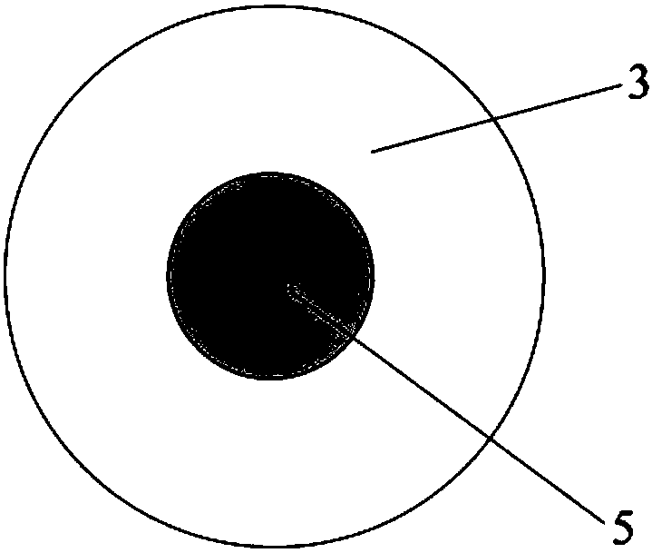
[0036] C. On the original model, set the end face of the bottom 3 side close to the main shaft 5 as follows Figure 4 and Figure 5 For the circular groove with a semicircular section shown, the radius of the circle and the position of the center of the circle are used as design parameters.

[0037] D. Calculate the corresponding spindle bending deformation, Mises stress, contact pressure and friction torque at different radii and different center positions as shown in Table 2.

[0038] E. Make a comprehensive comparison of the data in Table 2 (the mo...


PUM


Abstract

The invention belongs to the technical field of design, manufacture and assembly of large-scale mechanical equipment, and provides a design method for reducing an assembly stress of a main shaft and an impeller and bending deformation of the main shaft. A circular groove structure is arranged on one end surface, at a certain distance from the surface of the main shaft, of the hub bottom of the impeller; the groove shape is determined according to specific product specifications and processing equipment conditions; and the main shaft bending deformations, Mises stresses, contact pressures and maximum transferable friction torques of five different shapes of cross sections are calculated by using the large commercial finite element software ABAQUS, and the optimal circular groove shape and size matched with the main shaft and the impeller are selected. The design method can effectively reduce the bending deformation during hot assembly of the main shaft without significantly reducing thefriction torque and can also greatly reduce the stress concentration so as to provide a good solution for solving the bending deformation problem and the stress concentration problem of the main shaft and the impeller of a large-scale rotating machine during interference assembly.

Description

technical field [0001] The invention belongs to the technical field of design, manufacture and assembly of large-scale mechanical equipment, and relates to a design method for reducing the assembly stress of the main shaft-impeller and the bending deformation of the main shaft. Background technique [0002] The main shaft-impeller is the core component of many large rotating machines. In order to improve the operating efficiency and save energy, this kind of equipment is constantly developing in the direction of high speed, large size and super large size, and the corresponding main shaft-impeller size is also getting larger and larger. The speed is getting higher and higher. The most representative ones are large centrifugal compressors that are widely used in petrochemical, metallurgy, air separation, pharmaceutical and national defense research and other fields. For example, the total length of the main shaft of an MCO centrifugal compressor unit reaches 5.933m, and the o...

Claims


Application Information

Patent Timeline
Patent Type & Authority Applications(China)
IPC IPC(8): G06F17/50
CPCG06F30/17G06F30/23
Inventor 马国军吴承伟刘向东杨树华郭峰包翠敏王新超
Owner DALIAN UNIV OF TECH
Why Eureka
Try Eureka