Bipolar lead-acid storage battery

A lead-acid battery, bipolar technology, applied in battery pack components, electrode carriers/current collectors, circuits, etc., can solve problems such as inability to charge and discharge large currents, inability to obtain safety guarantees, and difficult manufacturing processes , to achieve the effect of simple structure, high reliability and easy maintenance

Active Publication Date: 2018-02-16
谢凡
View PDF8 Cites 3 Cited by
  • Summary
  • Abstract
  • Description
  • Claims
  • Application Information

AI Technical Summary

Problems solved by technology

[0002] In recent years, in order to protect the environment and reduce carbon dioxide emissions, more new energy sources have been developed and utilized, especially in the automotive industry, but high-performance secondary batteries are still the current technical bottleneck. Practice in recent years has proved that lithium-ion batteries are Because of its structure and materials, it cannot be charged and discharged with a large current, and cannot be guaranteed. Therefore, from the current situation, bipolar lead-acid batteries will be the best choice for batteries in the automotive industry. However, they have not yet been developed at home and abroad. A mature and practical bipolar lead-acid battery has been produced, and the bipolar plate structure is the biggest difficulty. The current public plate structure is relatively complicated, the production process is difficult, the cost is high, and the reliability is low.

Method used


Image

  • Bipolar lead-acid storage battery
  • Bipolar lead-acid storage battery
  • Bipolar lead-acid storage battery

Examples


Embodiment Construction

[0019] The present invention will be further described in detail below in conjunction with the accompanying drawings and specific embodiments.

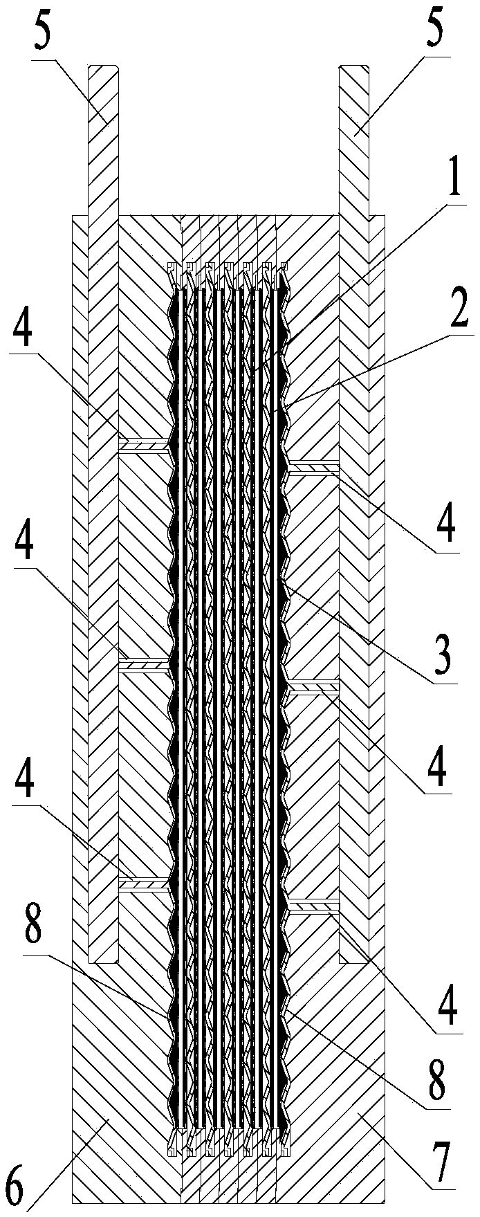
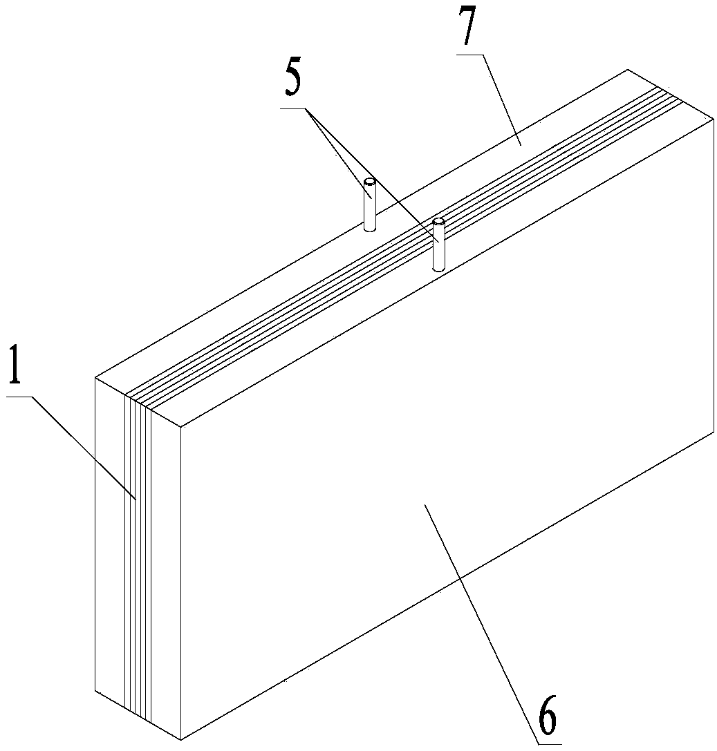
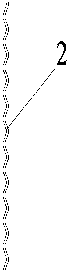
[0020] Such as figure 1 and figure 2 As shown, the bipolar lead-acid storage battery of the present invention comprises a positive side pole plate 6, a negative side pole plate 7 and a bipolar side grid 1 arranged between the positive side pole plate 6 and the negative side pole plate 7. The polar side grid 1 includes several pole plates 2 arranged side by side, and the pole plates 2 are lead strips, combined with image 3 As shown, the pole plate 2 is a corrugated pole plate 2 with a sinusoidal wave cross section formed by extrusion, and the two sides of the pole plate 2 are respectively coated with positive electrode paste and negative electrode paste and cured, and each two adjacent pole plates 2 There is a diaphragm 3 between them, the thickness of the diaphragm 3 is 1.2mm, the two sides of the diaphragm 3 are respectively in c...


PUM

PropertyMeasurementUnit
thicknessaaaaaaaaaa
thicknessaaaaaaaaaa

Abstract

The invention relates to the field of storage batteries, and discloses a bipolar lead-acid storage battery. The bipolar lead-acid storage battery comprises a positive side polar plate, a negative sidepolar plate and a bipolar side plate grid, wherein the bipolar side plate grid comprises a plurality of polar plates arrayed side by side; positive lead plaster and negative lead plaster are respectively coated on the two faces of the polar plates, and solidified; a membrane is padded between every two adjacent polar plates; the two sides of the membranes are respectively contacted with the positive lead plaster and the negative lead plaster; a plurality of wiring terminals are respectively welded on two polar faces of the bipolar side plate grid; the wiring terminals on each polar face are connected by leading-out wires; frames of the bipolar side plate grid are subjected to injection molding to form plastic frames; the leading-out wires are led out of the plastic frames at the upper part of the bipolar side plate grid; the positive side polar plate and the negative side polar plate are respectively formed by injection molding of the two polar faces of the bipolar side plate grid welded with the wiring terminals; the positive lead plaster and the negative lead plaster are respectively coated on one face of the bipolar side plate grid not connected with the wiring terminals; and an electrolyte is contained in the bipolar side plate grid. The bipolar lead-acid storage battery is simple in structure, convenient to manufacture, low in cost and high in reliability.

Description

technical field [0001] The invention relates to the field of accumulators, in particular to a bipolar lead-acid accumulator. Background technique [0002] In recent years, in order to protect the environment and reduce carbon dioxide emissions, more new energy sources have been developed and utilized, especially in the automotive industry, but high-performance secondary batteries are still the current technical bottleneck. Practice in recent years has proved that lithium-ion batteries are Because of its structure and materials, it cannot be charged and discharged with a large current, and cannot be guaranteed. Therefore, from the current situation, bipolar lead-acid batteries will be the best choice for batteries in the automotive industry. However, they have not yet been developed at home and abroad. Mature and practical bipolar lead-acid batteries have been produced, and the bipolar plate structure is the biggest difficulty. The current public plate structures are relative...

Claims


Application Information

Patent Timeline
Patent Type & Authority Applications(China)
IPC IPC(8): H01M4/73H01M2/18H01M50/40H01M50/403H01M50/409
CPCH01M4/73H01M50/463Y02E60/10
Inventor 谢凡
Owner 谢凡
Why Eureka
Try Eureka