
High-isolation coaxial radial power divider

A technology with radial power and high isolation, applied in waveguide devices, electrical components, connecting devices, etc., can solve problems such as increased cost, reduced stability and reliability, and limited output power of a single tube to achieve improved isolation Accuracy, stable return loss, low loss effect

Inactive Publication Date: 2018-02-16
UNIV OF ELECTRONICS SCI & TECH OF CHINA
View PDF2 Cites 8 Cited by
  • Summary
  • Abstract
  • Description
  • Claims
  • Application Information

AI Technical Summary

Problems solved by technology

In recent years, the requirements for the output power of amplifiers in various fields are getting higher and higher. However, due to the limited output power of a single tube, increasing the output power of a single tube not only increases the cost, but also leads to a decrease in stability and reliability as the output power increases.

Method used


Image

  • High-isolation coaxial radial power divider
  • High-isolation coaxial radial power divider
  • High-isolation coaxial radial power divider

Examples


Embodiment

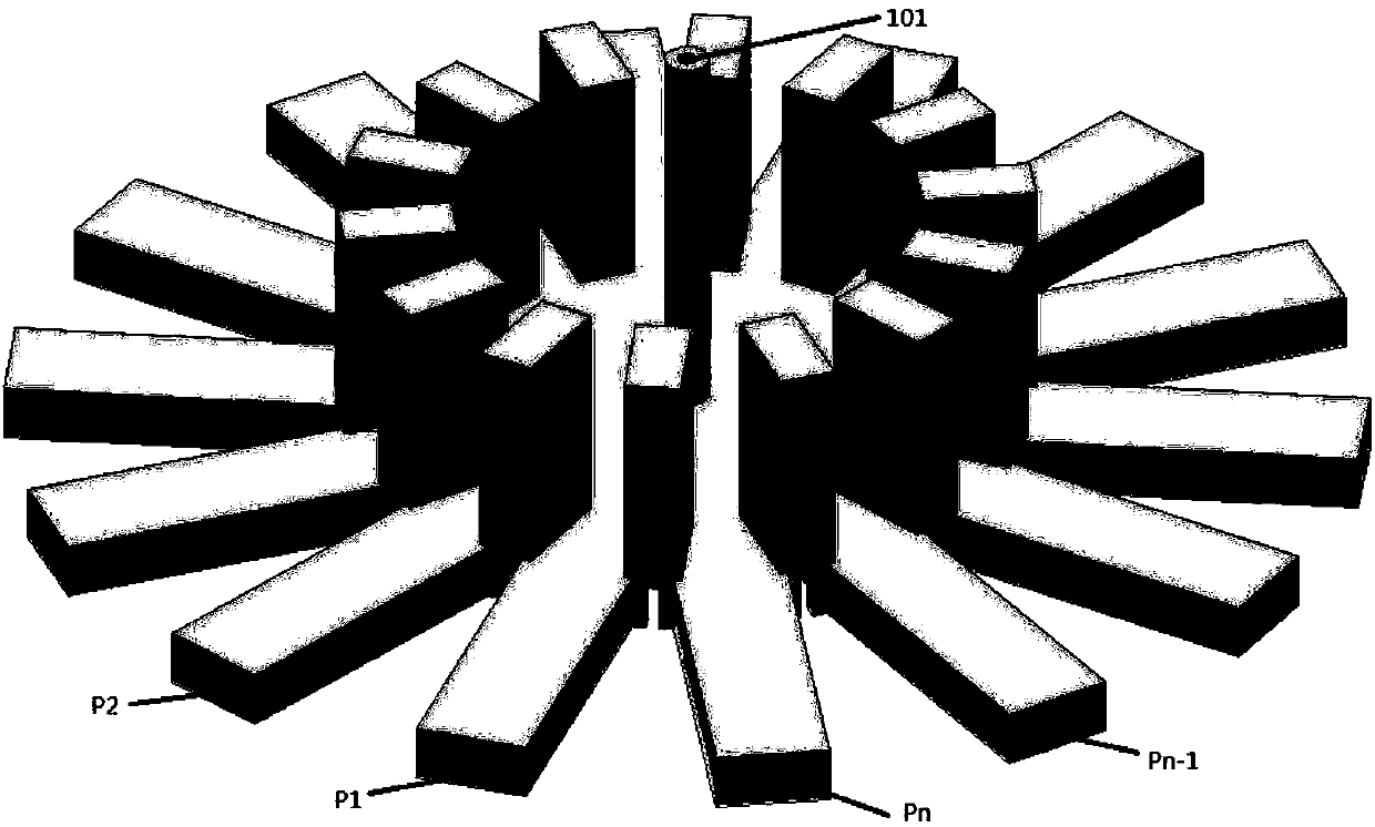
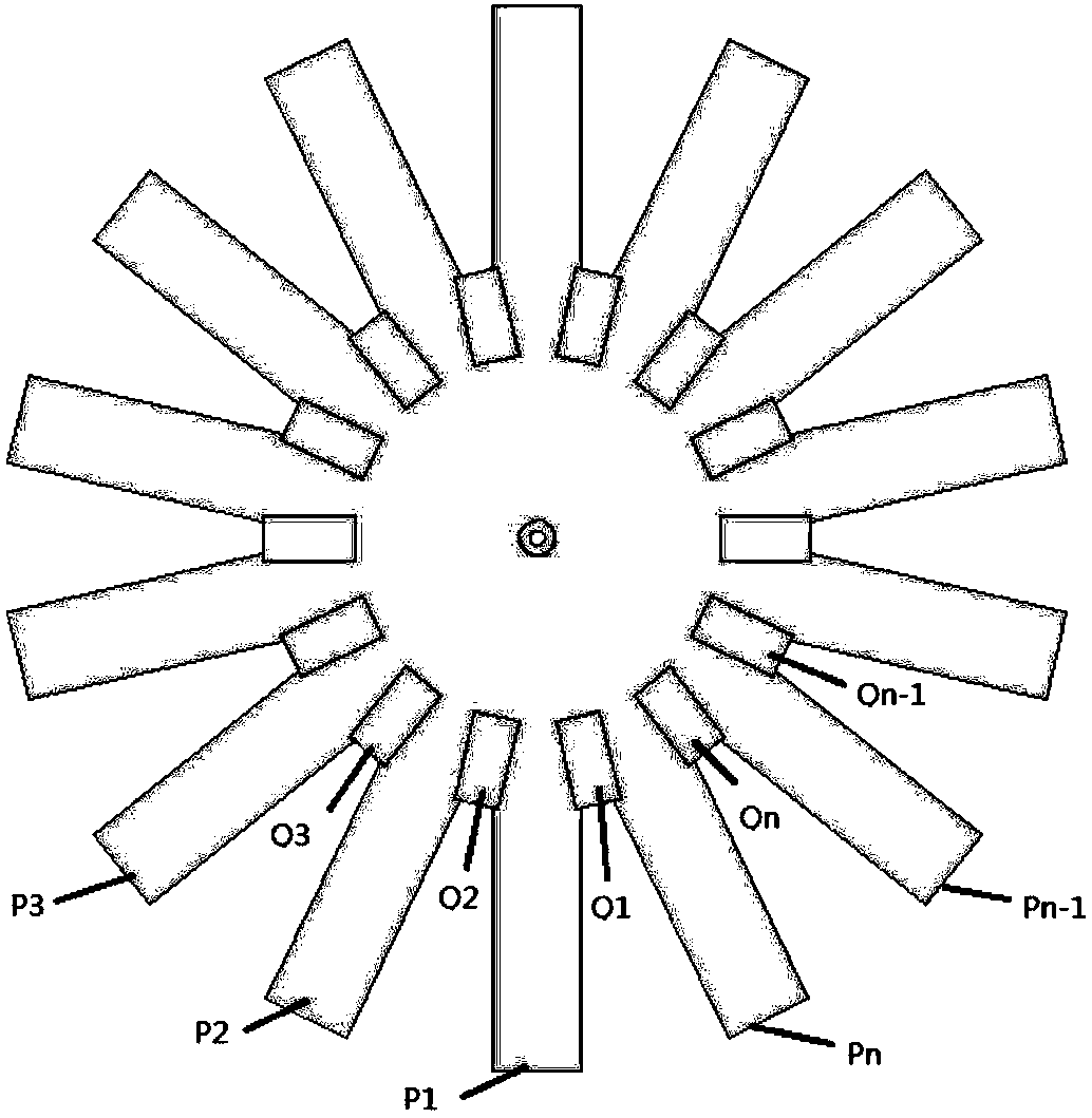
[0025] In this example, if figure 1 As shown in the structure, the radial waveguide power divider works in the W frequency band, the working frequency is 87-97GHz, the input port 101 is a coaxial line, the outer radius of the coaxial line is 0.5mm, and the inner radius is 0.2mm; the output ports P1, P2 , ..., Pn is a BJ100 standard rectangular waveguide with a size of 2.54mm×1.27mm. The TEM wave signal is input from port 101, and converted into TE that can propagate in the rectangular waveguide BJ100 through the third-order gradient conical matching structure connected to the other port of the coaxial line. 10 Mode, and then through the isolator Q1, Q2, ..., Qn and the matching structure between the output port and the isolation port, the output signal is output through the output port P1, P2, ..., Pn in an orderly and stable manner, with equal amplitude and phase.

[0026] In this example, n=14, the return loss curve of the overall high-isolation radial power divider is as ...


PUM


Abstract

The present invention discloses a high-isolation coaxial radial multipath power divider suitable for a millimeter wave frequency. The power divider comprises a coaxial line input port, three circulartruncated cone matching structures, a plurality of rectangular waveguide output ports (n>=2), isolation ports and isolation port matching structures. TEM waves in a coaxial line are combined to TE10 modes in rectangular waveguides through the circular truncated cone matching structures, mode conversion and energy distribution of the TEM waves in the coaxial line to the TE10 modes of the n rectangular waveguides is achieved through guidance of the isolation ports, and signals of each output port are equal in amplitude and in phase. Isolation ports are added to have a high isolation between theoutput ports, compared to structures such as a circular waveguide, the high-isolation coaxial radial power divider employs a coaxial line and employs main mode transmission of the coaxial line, the mode is pure to avoid interference of a higher mode, and the structure is especially suitable for a power distribution / synthesis circuit with a millimeter wave frequency and can be extended to a higherfrequency.

Description

technical field [0001] The invention relates to the technical field of millimeter wave power synthesis, in particular to a radial power divider with high isolation. Background technique [0002] Millimeter-wave power amplifiers are the core components of millimeter-wave systems and research hotspots in the millimeter-wave field. They are widely used in military radar systems, radio astronomy, space, and short-distance wireless high-speed transmission. They have great application value and market prospects. In recent years, the requirements for amplifier output power in various fields are getting higher and higher. However, due to the limited output power of a single tube, increasing the output power of a single tube not only increases the cost, but also reduces stability and reliability with the increase of output power. Therefore, it is an inevitable choice to adopt the power synthesis technology combining multiple coherent amplifiers. This technology can double the power o...

Claims


Application Information

Patent Timeline
Patent Type & Authority Applications(China)
IPC IPC(8): H01P5/16
CPCH01P5/16
Inventor 詹铭周何望栋龚燕林
Owner UNIV OF ELECTRONICS SCI & TECH OF CHINA
Learn More