AC synchronous generator rotor full-automatic winding machine

A fully automatic winding machine and synchronous generator technology, which is applied in the manufacture of motor generators, electric components, electrical components, etc., can solve the problems of inability to automatically change poles, inability to automatically reverse magnetic poles, etc., to improve work efficiency It is related to product quality, solves the problem of poor winding quality, and ensures the effect of uniformity

Pending Publication Date: 2018-02-16
王江锋
View PDF0 Cites 11 Cited by
  • Summary
  • Abstract
  • Description
  • Claims
  • Application Information

AI Technical Summary

Problems solved by technology

[0008] In view of this, the purpose of the present invention is to overcome the deficiencies of the prior art and provide a fully automatic winding machine for the rotor of an AC synchronous generator to solve the problem that the existing winding machine cannot automatically change the pole of the rotor blade and cannot use The problem with the automatic reversal of the magnetic poles

Method used


Image

  • AC synchronous generator rotor full-automatic winding machine
  • AC synchronous generator rotor full-automatic winding machine
  • AC synchronous generator rotor full-automatic winding machine

Examples


Embodiment 1

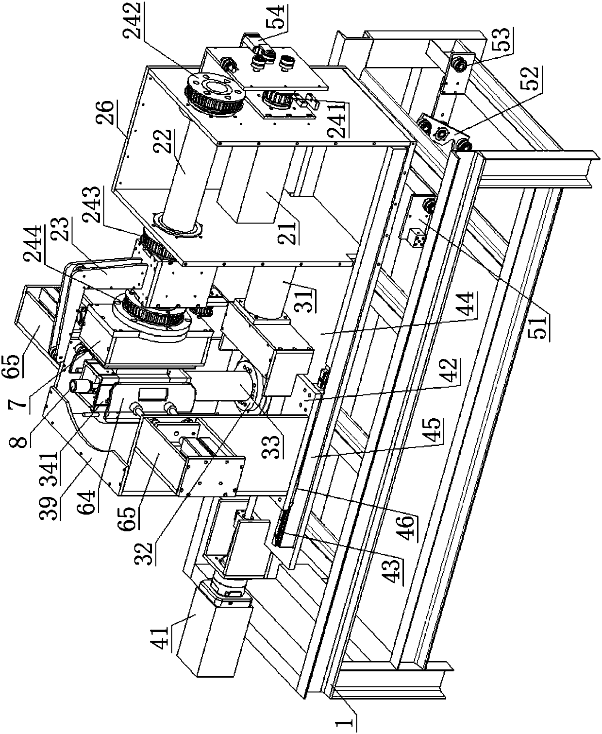
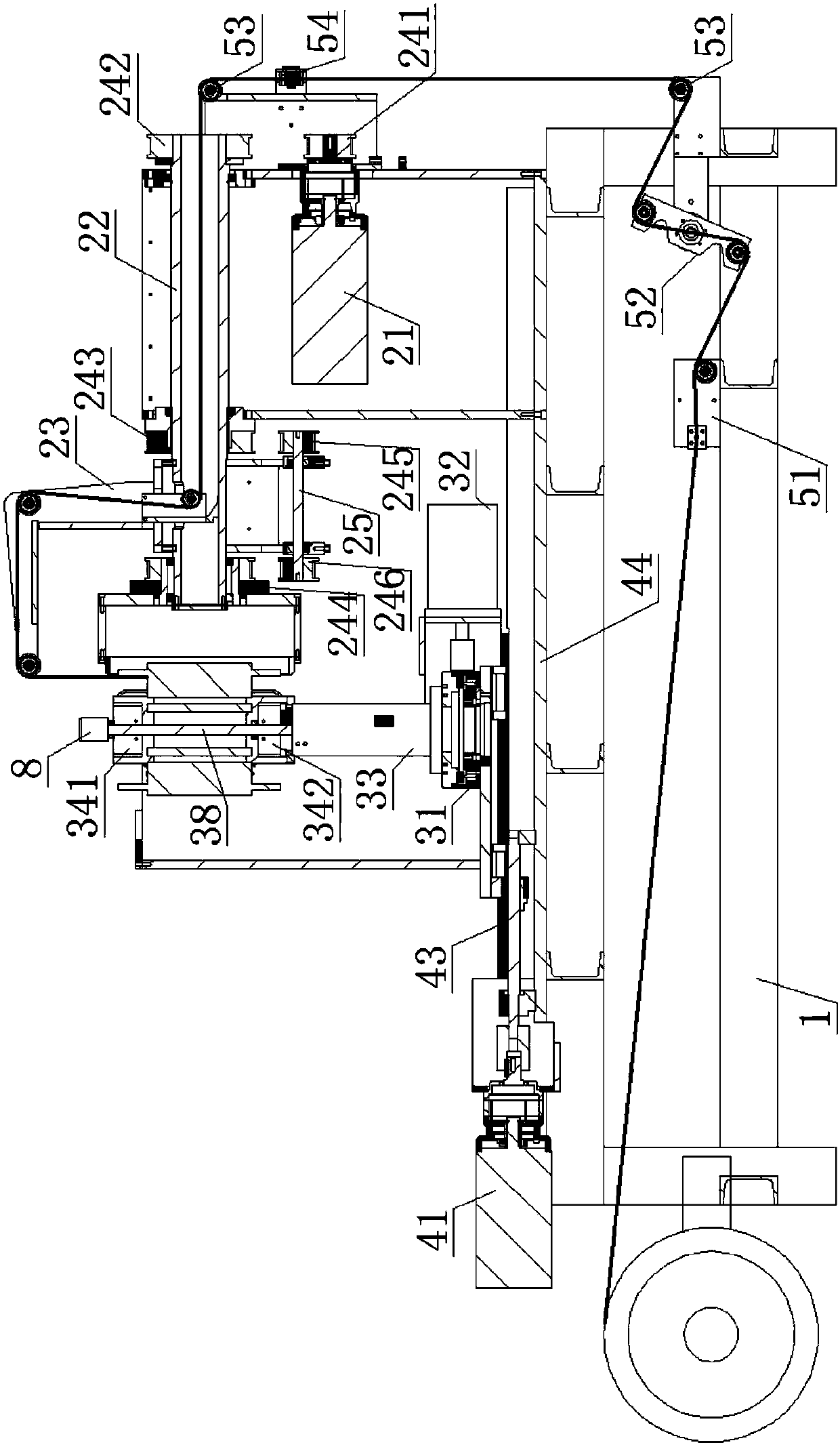
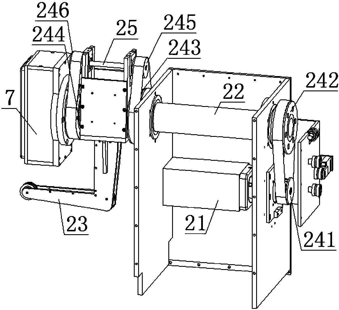
[0037] A fully automatic winding machine for the rotor of an AC synchronous generator, such as Figure 1 to Figure 5 As shown, it includes a base 1 welded by channel steel, a reversible winding device and a pole changing device capable of switching rotor blades. Such as Figure 6Shown is a schematic diagram of the structure of the generator rotor. The rotor has pole wings 9, and the rotor is fastened in the pole changing device. Wherein, winding device comprises winding motor 21, hollow shaft 22, winding rod 23 and winding housing 26, and winding rod 23 is installed on the outside of winding housing 26, and winding motor 21 and hollow shaft 22 are installed in parallel Inside the wire casing 26 , the winding casing 26 is fixedly installed on the base 1 . The output shaft of the winding motor 21 is connected with the a synchronous wheel 241 positioned at the outside of the winding shell 26, and one end of the hollow shaft 22 is connected with the b synchronous wheel 242 positi...

Embodiment 2

[0042] As preferably, in order to realize the present invention better, optimize further on the basis of above-mentioned embodiment, especially adopt following setting structure:

[0043] Such as figure 1 , figure 2 As shown, in order to arrange the enameled wires wound on the rotor pole wings 9 evenly and tightly, the present invention also adds a cable arrangement device, which includes a cable arrangement motor 41 installed on the base 1 and a slide table main board 44. Main beams 45 are provided on both sides of the platform main board 44, and slide rails 43 are provided on the main beams 45; a slide table 42 is fixed on the bottom of the pole-changing shell 39, and the four corners of the bottom of the slide table 42 are respectively provided with sliding rails 43. The chute 46, the cable motor 41 drives the slide table 42 to move on the slide table main board 44 through the cooperation of the slide rail 43 and the chute 46, so that the pole wing 9 of the rotor can mov...

Embodiment 3

[0045] As preferably, in order to realize the present invention better, optimize further on the basis of above-mentioned embodiment, especially adopt following setting structure:

[0046] Such as figure 1 , figure 2 As shown, in order to tighten the enameled wire and make the tension force of the enameled wire to be wound controllable, the present invention also adds a tensioning device, which includes a motor-driven clamping plate 51, a plurality of rollers 53 forming the path of the enameled wire, Torsion spring 52 and tension sensor 54, clamping plate 51 is installed on the enameled wire path, and torsion spring 52 is installed on the enameled wire path between tensioning clamping plate 51 and winding rod 23, and tension sensor 54 is installed on torsion spring 52 and winding rod 23 The enameled wire path between them, and the tension sensor 54 is electrically connected with the drive motor of the splint 51 .

[0047] The stretching splint 51 clamps the enameled wire, a...


PUM


Abstract

The invention relates to a fully automatic winding machine for the rotor of an AC synchronous generator, which includes a base, a winding device capable of forward and reverse rotation, and a pole changing device. Fixed in the pole changing device, the pole wings of the rotor are aligned with the winding direction of the winding device, the winding device winds the pole wings of the rotor, and the pole changing device drives the rotor to rotate. The rotor is fastened to the pole-changing device, and the winding device winds the pole wings of the rotor. When the winding of one pole wing is completed, the pole-changing device drives the rotor to rotate so that the next pole wing is aligned with the winding direction of the winding device and continues to rotate. The pole wing is wound. At this time, the winding device is reversed, so that the wound enameled coil is reversed, and the magnetic pole of the rotor is automatically reversed. The entire winding machine automatically completes all the work of rotor winding, without manual pole changing operation, without cutting the enameled wire end, and without welding the enameled wire end, which improves the work efficiency and product quality of generator rotor production.

Description

technical field [0001] The invention relates to the technical field of generator rotor winding equipment, in particular to a fully automatic winding machine for an AC synchronous generator rotor. Background technique [0002] Such as Figure 6 As shown, it is the rotor of an AC synchronous generator. Coils are wound on the pole wings of the rotor. Before the emergence of automatic winding machines, the winding is usually done manually, which is not only time-consuming and laborious, but also has a high rate of defective products. With the advent of the automatic winding machine, this situation has been greatly improved. The automatic winding machine not only winds neatly, but also has a very high winding efficiency. At the same time, the defective rate has also been effectively controlled, which is very It is conducive to large-scale and large-scale production. In practice, using a fully automatic winding machine to wind the rotor of the generator needs to meet the requirem...

Claims


Application Information

Patent Timeline
Patent Type & Authority Applications(China)
IPC IPC(8): H02K15/08
CPCH02K15/08
Inventor 王江锋
Owner 王江锋
Why Eureka
Try Eureka