Piezoelectric energy harvester applied to pipeline fluid monitoring

A piezoelectric energy harvesting and pipeline technology, which is applied in the field of fluid pipeline monitoring systems and piezoelectric energy harvesters, can solve the problems of inability to complete remote transmission of monitoring information, affecting the normal operation of the monitoring system, and limited use time. The effect of simple process, low cost and strong power generation capacity

Active Publication Date: 2018-02-16
XIANGTAN UNIV
View PDF4 Cites 5 Cited by
  • Summary
  • Abstract
  • Description
  • Claims
  • Application Information

AI Technical Summary

Problems solved by technology

The method of laying cables is costly, and has been cut off by criminals, which affects the normal operation of the monitoring system; while using batteries for power supply, the...

Method used


Image

  • Piezoelectric energy harvester applied to pipeline fluid monitoring
  • Piezoelectric energy harvester applied to pipeline fluid monitoring
  • Piezoelectric energy harvester applied to pipeline fluid monitoring

Examples


Embodiment Construction

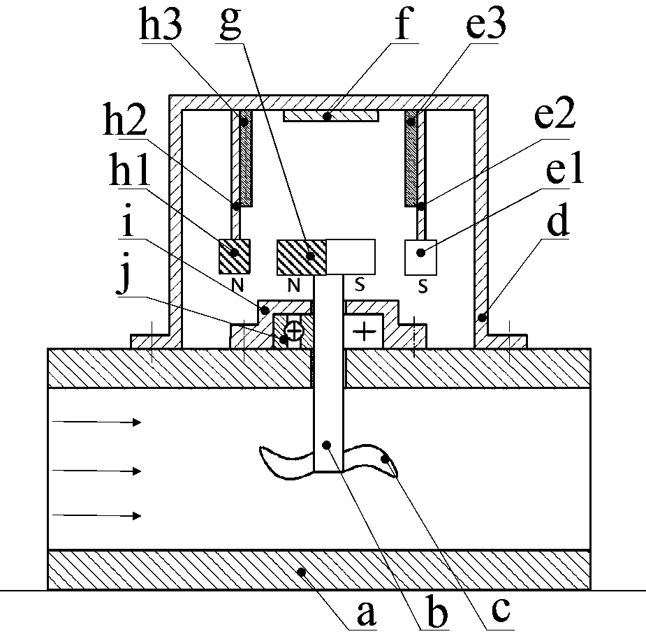
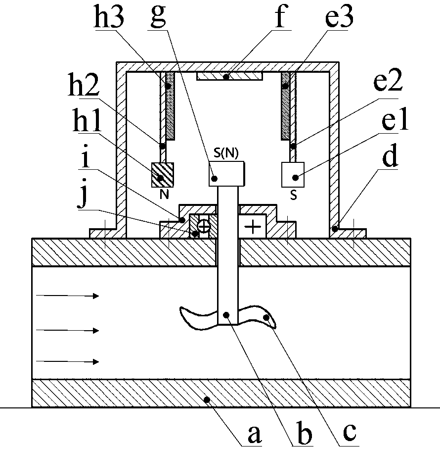
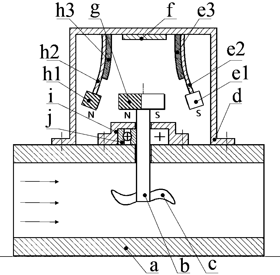
[0014] One end of the inner wall of the pipe a through the axis b is equipped with an impeller c, which is horizontally located in the center of the pipe. The shaft b is vertically installed in the hole of the pipe a, and the other end of the shaft b is equipped with two poles (including N and S poles) bar-shaped permanent magnet g, which is located on the outer wall of the pipe a. The bearing j and the bearing seat i are installed directly above the pipe a, and are fastened to the outer wall of the pipe a with screws. Piezoelectric vibrator 1 is formed by bonding metal substrate e2, piezoelectric sheet e3 and unipolar (N) bar-shaped permanent magnet e1. One end of metal substrate e2 is connected to the inside of metal shell d by screws, and piezoelectric sheet e3 is bonded on the surface , the piezoelectric vibrator II is made of a metal substrate h2, a piezoelectric sheet h3 and a unipolar (N) strip permanent magnet h1. One end of the metal substrate h1 is connected to the i...


PUM


Abstract

The invention relates to a piezoelectric energy harvester applied to pipeline fluid monitoring, and belongs to the fields of new energy and piezoelectric power generation. Impellers are positioned onthe inner wall, which passes through one end of a shaft, of a pipeline, and are positioned in the center of the pipeline; strip-shaped permanent magnets are arranged at the other end of the shaft, andare positioned on the outer wall of the pipeline; the shaft is supported by a bearing and a bearing pedestal and vertically mounted above the pipeline; each piezoelectric vibrator consists of a metalsubstrate, a piezoelectric sheet and the strip-shaped permanent magnets in a gluing manner; one end of the metal substrate is connected with the interior of the metal shell, the free end is connectedwith the permanent magnets, and the surface is glued with the piezoelectric sheet; and a circuit board is just mounted in the center of the interior of the shell, and the shell is mounted on the upper part of the pipeline. The piezoelectric energy harvester has the characteristics and advantages as follows: the stable piezoelectric energy harvester is formed by interaction force between the permanent magnets; and the piezoelectric energy harvester is simple in structure and process, low in cost, free of accelerated speed sudden change, high in vibration stability, high in power generation capability and high in reliability, and capable of improving electric energy production by increasing the number and prolonging the piezoelectric vibrators.

Description

technical field [0001] The invention belongs to the field of new energy and piezoelectric power generation, and in particular relates to a piezoelectric energy harvester applied to pipeline fluid monitoring, which is used in a fluid pipeline monitoring system. Background technique [0002] Pipeline fluid (including oil and gas pipelines, South-to-North Water Diversion Project, West-East Gas Transmission Project.) is the lifeblood of national energy and economic construction. Due to natural corrosion, natural force majeure, and especially man-made theft, pipeline fluid leakage incidents occur from time to time, which not only cause huge economic losses, but also cause serious pollution to the surrounding natural environment. In the past, regular manual inspections were often used to maintain fluid pipelines. However, due to the long laying distance and often in inaccessible or inconvenient places, regular inspections are difficult to find leaks and repair them in time. Theref...

Claims


Application Information

Patent Timeline
IPC IPC(8): H02N2/18
CPCH02N2/185H02N2/186
Inventor 郑学军王永峰苏亮
Owner XIANGTAN UNIV
Why Eureka
Try Eureka