Numerical control current conversion system adopting parallel decoding mode

A technology of current conversion and mode, which is applied in the direction of analog-to-digital converter, analog-to-digital conversion, code conversion, etc., can solve the problems of slow driving ability and operation speed, inconvenient general use, and low precision, so as to achieve fast load dynamic response and avoid The effect of concentrated heat generation and high response speed

Active Publication Date: 2018-02-16
VOLT ELECTRONICS SUZHOU CO LTD
View PDF4 Cites 0 Cited by
  • Summary
  • Abstract
  • Description
  • Claims
  • Application Information

AI Technical Summary

Problems solved by technology

The general constant current source is often a fixed output current value, or only several different current values, which is not convenient for general use.
[0004] The existing constant current source usually uses a switching power supply to cooperate with high-speed or high-precision analog-to-digital conversion chips. At the same time, it has the requirements of high precision and high speed, and the analog-to-digital conversion chip with high output precision has slow driving ability and operation speed, while the analog-to-digital conversion chip with high operation speed and strong driving ability has low precision.
The limited area of ​​the chip and the width of the internal traces limit the speed and precision performance of the analog-to-digital conversion chip. At the same time, the output of the switching power supply takes a long time to set up, the response lags, the dynamic response is slow, and the problems of concentrated heat dissipation cannot be solved.

Method used


Image

  • Numerical control current conversion system adopting parallel decoding mode
  • Numerical control current conversion system adopting parallel decoding mode
  • Numerical control current conversion system adopting parallel decoding mode

Examples


Embodiment

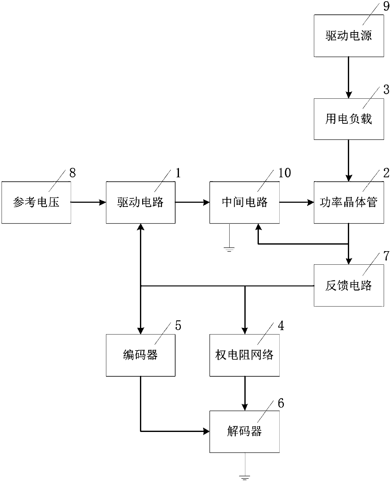
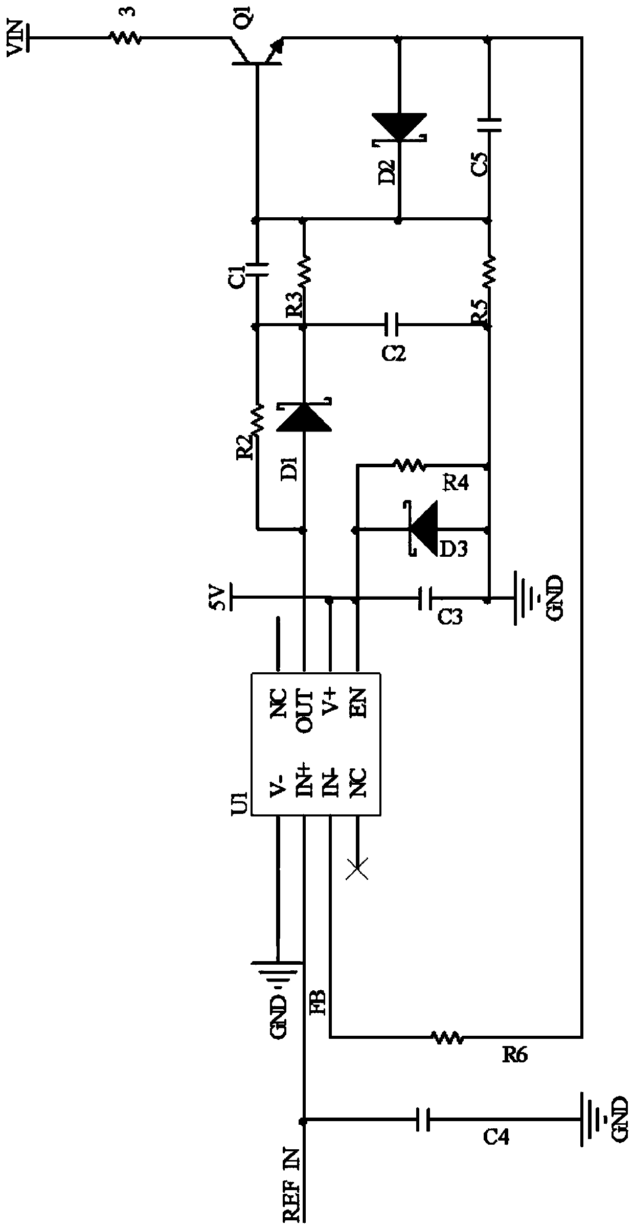
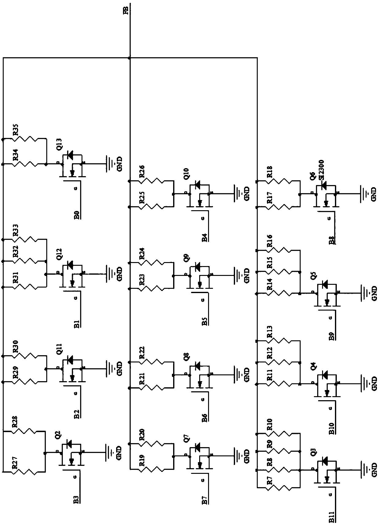
[0026] refer to Figure 1 ~ Figure 3 As shown, this embodiment discloses a digitally controlled current conversion system using a parallel decoding mode, including:

[0027] Drive circuit 1: The drive circuit 1 includes an operational amplifier U1, the input terminal IN+ of the operational amplifier U1 is connected to the reference voltage 8, the reference voltage 8 inputs the reference signal REF IN, and a fourth capacitor is connected between the contact of the reference voltage 8 and the input terminal IN+ and the ground C4. The operational amplifier U1 is externally connected with a power supply for its operation, the enabling terminal EN of the operational amplifier U1 is connected to the power supply, and a third capacitor C3 is connected between the enabling terminal EN and the ground. The third capacitor C3 and the fourth capacitor C4 are used to filter out AC components in the power supply and REF IN respectively, and the operational amplifier U1 has an operational a...


PUM


Abstract

The invention discloses a numerical control current conversion system adopting a parallel decoding mode. The numerical control current conversion system comprises a driving circuit and a power transistor, the driving circuit is connected with the power transistor, the feedback circuit is connected between the driving circuit and the power transistor, the power transistor is connected with a powerutilization load and a driving power supply in series in sequence; a right resistor network is connected between an output end of the feedback circuit and the ground, the right resistor network is composed of multiple levels of resistors connected in parallel, the resistance of the resistors changes in equal proportion level by level, and the right resistor network is used for adjusting the size of the current flowing by the power utilization load and converting the current feedback on the feedback circuit into voltage feedback; a decoder is connected between each level of resistor of the right resistor network and the ground; and an encoder is connected between the input end of the right resistor network and the decoder. The conversion precision is high, the conversion speed is high, thedriving ability is high, the output has a order of magnitudes, and the heat dissipating effect is good.

Description

technical field [0001] The invention relates to the field of analog-to-digital conversion drives, in particular to a numerical control current conversion system adopting a parallel decoding mode. Background technique [0002] The use of constant voltage source drive in the industrial and automotive industries usually cannot guarantee the stability of the sensor, and affects the reliability and life of the sensor. Therefore, it is suitable to be driven by a constant current source, and the conventional DAC (Digital to Analog Converter) cannot meet the requirements of conversion accuracy, conversion speed and driving capability at the same time. [0003] In general detection circuits, in order to ensure the stability of detection parameters, the driving constant current source must be highly stable, highly reliable, and of high output quality. The essence of the constant current source is to use the device to feedback the current and dynamically adjust the power supply state ...

Claims


Application Information

Patent Timeline
Patent Type & Authority Applications(China)
IPC IPC(8): H03M1/12
CPCH03M1/1205
Inventor 刘立峰李志强曹箫洪王一波
Owner VOLT ELECTRONICS SUZHOU CO LTD
Why Eureka
Try Eureka