

LTE230 power system private network optimization method
A power system and optimization method technology, applied in the direction of electrical components, network planning, network traffic/resource management, etc., to achieve the effect of convenient management, convenient maintenance, and reduced rain attenuation
- Summary
- Abstract
- Description
- Claims
- Application Information
AI Technical Summary
Problems solved by technology
Method used
Image

Examples
Embodiment 1
[0032] A kind of LTE230 power system private network optimization method, is characterized in that, following steps:
[0033] A. Establish an LTE230 power system private network, adjust the antenna and transmission power to achieve the best coverage, and balance the capacity of the base station;
[0034] B. Execute interference location investigation and make adjustments;
[0035] C. Optimize the stability of the core network system through active and standby configurations.
[0036] In step A, during the project construction period, according to the wireless environment, the signals in the most places meet the minimum level requirements required by the business by adjusting the antenna and adjusting the power.
[0037] In step B, an outfield drive test is also carried out to determine the longitude, latitude and range of the weak coverage area with low SINR, and a network adjustment plan and a blind filling plan are carried out; the network adjustment plan includes: the base...
Embodiment 2
[0057] This embodiment is basically the same as Embodiment 1, the difference is that, after the preliminary planning is completed, the base station combinations that meet the standards in the top ranks of the transmission degree and whose transmission degree is greater than the set standard are selected as the key resource base station combination to carry out the key resource transmission degree sort;
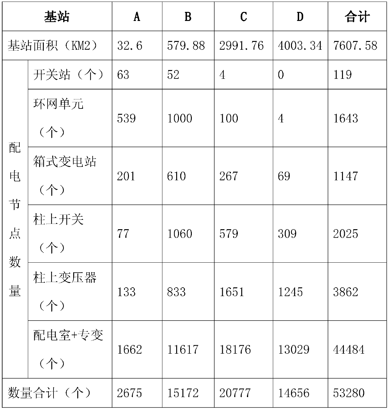
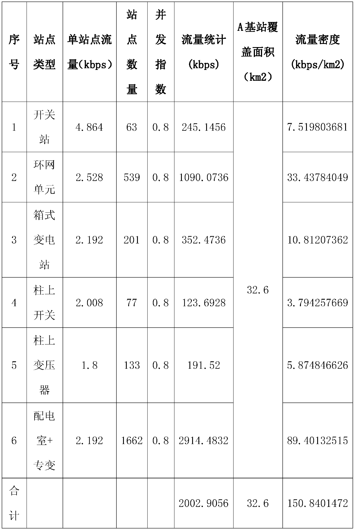
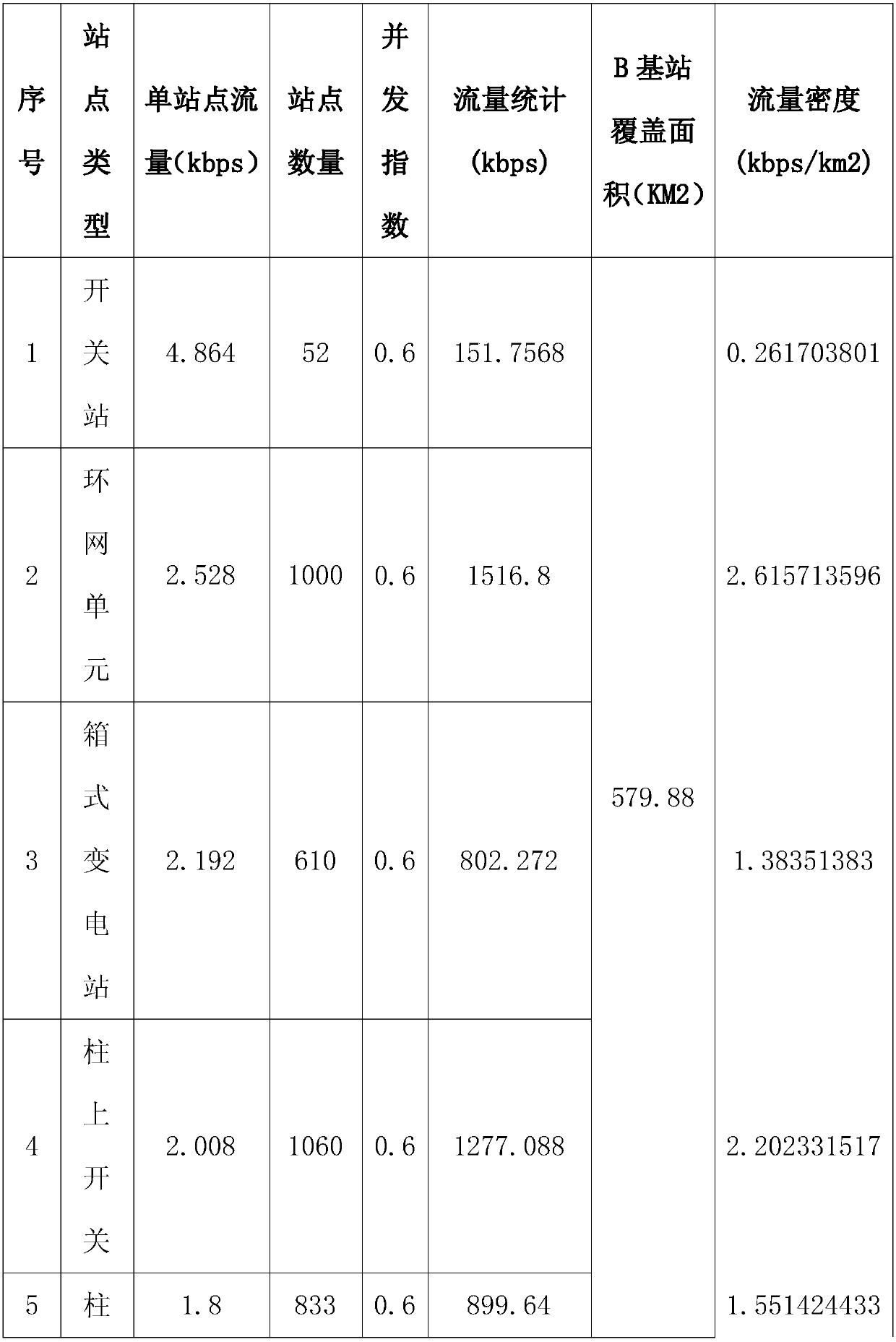
[0058] Sub-step 1 of key resource transmission degree sorting: calculate key resource flow density ToA in each grid; ToA z =K z ×(T1×N1+T2×N2+...+Tm×Nm) / S; ToA z is the key resource flow density in each grid, K z is the concurrency coefficient of key resource services in the grid area, which is manually set; Tm is the information communication demand value of each key resource terminal, Nm is the number of key resource terminals corresponding to Tm type in the grid area, and m is less than or equal to n;
[0059] Key resource transmission degree sorting sub-step 2: Calculat...
Embodiment 3
[0062] This embodiment is basically the same as Embodiment 1, the difference is that in step C, the grids whose flow density is greater than the set value in all grids are selected as the key grids, and the key grids in each base station combination are calculated. Repeated coverage number, calculate the number of key grids whose repeated coverage number is greater than 2 in the base station combination as an auxiliary value, when the total transmission degree difference of the base station combination is less than the set threshold, select the base station combination with the least auxiliary value and sort it in forward.
PUM
 Abstract
Description
Claims
Application Information