Piezoelectric Element And Device Using Same
A piezoelectric element and equipment technology, applied in the field of fibrous piezoelectric elements, can solve the problems of output signal, no indication, etc.
- Summary
- Abstract
- Description
- Claims
- Application Information
AI Technical Summary
Problems solved by technology
Method used
Image
Examples
Embodiment 1)
[0782] The conductive fiber 100B was knit while winding eight piezoelectric fibers 100A, thereby obtaining a cord-shaped covered fiber 1003 of a circular-wound material with a length of 10 m. Here, the volume resistivity of the conductive fiber 100B in the coated fiber 1003, that is, the silver-plated nylon fiber is 1.1×10 -3 Ω·cm. Thereafter, one end of the piezoelectric fiber 100A covering the surface of the fiber 1003 was removed to expose the conductive fiber 100B, thereby obtaining a piezoelectric element. the piezoelectric element through image 3 The structure as shown was evaluated for piezoelectric characteristics.
[0783] When the measurement sample 1004 is traced using this piezoelectric element, voltages different from each other can be confirmed by the portion of the base plate 104a and the overlapping portion of the two plates 104a, 104b.
[0784] In addition, the piezoelectric characteristics of the piezoelectric element were evaluated after rubbing 2000 tim...
Embodiment 2)
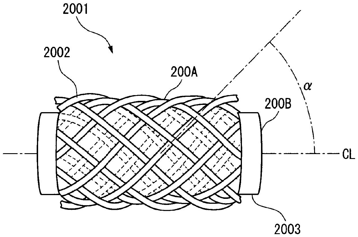
[0807] The conductive fiber 200B in the cord-shaped piezoelectric element 2001 was connected as a signal line to an oscilloscope (a digital oscilloscope DL6000 series product name "DL6000" manufactured by Yokogawa Electric Co., Ltd.) via wiring and a 1000-fold amplification circuit. The wire-shaped piezoelectric element 2001 is bent by 90 degrees in an electromagnetic wave shielding box protected by a wire mesh that is grounded (grounded).
[0808] As a result, a potential difference of about 100 mV was detected with an oscilloscope as an output from the piezoelectric wire 2001 , and it was confirmed that a sufficiently large electrical signal could be detected by deformation of the piezoelectric wire 2001 .
Embodiment 3)
[0810] The conductive fiber 200B in the string-shaped piezoelectric element 2001 of the string-shaped piezoelectric element 2005 is connected as a signal line to an oscilloscope (Digital Oscilloscope DL6000 series product name of Yokogawa Electric Co., Ltd. "DL6000"). In addition, the conductive fibers 2008 of the weft of the cloth-shaped piezoelectric element 2005 are grounded as a ground (ground) line. In this state, the fabric-shaped piezoelectric element 2005 is bent at 90 degrees in a direction perpendicular to the wire-shaped piezoelectric element 2001 .
[0811] As a result, as an output from the wire-shaped piezoelectric element 2001 of the cloth-shaped piezoelectric element 2005, an electric signal with almost no noise was obtained by an oscilloscope, and a potential difference of about 100 mV was detected. From the above results, it was confirmed that a sufficiently large electrical signal can be detected with low noise by utilizing the deformation of the fabric-sha...
PUM
| Property | Measurement | Unit |
|---|---|---|
| chiral purity | aaaaa | aaaaa |
| length | aaaaa | aaaaa |
| diameter | aaaaa | aaaaa |
Abstract
Description
Claims
Application Information
 - R&D
- Intellectual Property
- Life Sciences
- Materials
- Tech Scout
- Unparalleled Data Quality
- Higher Quality Content
- 60% Fewer Hallucinations
Browse by: Latest US Patents, China's latest patents, Technical Efficacy Thesaurus, Application Domain, Technology Topic, Popular Technical Reports.
© 2025 PatSnap. All rights reserved.Legal|Privacy policy|Modern Slavery Act Transparency Statement|Sitemap|About US| Contact US: help@patsnap.com


