Dialysis tube applied to blood dialysis

A technology of hemodialysis and dialysis tubes, applied in the field of dialysis tubes, can solve the problems of increased treatment difficulty, large dialysis equipment, death, etc., and achieve the effects of reducing the incidence of blood infection, improving dialysis efficiency, and increasing dialysis area

Inactive Publication Date: 2018-02-23
成都测迪森生物科技有限公司
View PDF0 Cites 3 Cited by
  • Summary
  • Abstract
  • Description
  • Claims
  • Application Information

AI Technical Summary

Benefits of technology

This patented technology allows patients who require frequent treatment to have their own kidneydyled tubes attached to them throughout their lifetime without causing any harm themselves. These tubings allow water to flow inside while still allowing oxygen to pass into the lungs where they perform respiration efficiently. By adding this special material called chitamic quatimide-polymer (CQP) onto the surface of these tubing materials, there will enhance its ability to absorb large amounts of salts like calcium ion when needed. Additionally, the CQP coating helps reduce inflammation caused by excess fluid accumulation around the implanted parts. Overall, this new design enables efficient and safe medical treatments at home.

Problems solved by technology

The technical problem addressed in this patented text relates to improving the efficiency and effectiveness of medical procedures such as kidney disease treatments involving removing substances like urea nitrogen monoxides ("UNO") and drugs during haemodynexis processes due to increased risk of bleeding complications caused by prolonged exposures to these agents over an extended period of time.

Method used


Image

  • Dialysis tube applied to blood dialysis
  • Dialysis tube applied to blood dialysis
  • Dialysis tube applied to blood dialysis

Examples


Embodiment 1

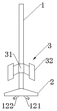
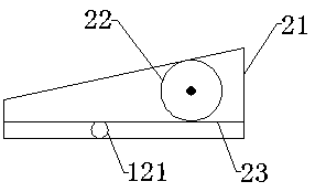
[0038] Such as Figure 1-3 As shown, the present embodiment provides a dialysis tube for hemodialysis, which includes a dialysis part 1 , a connection part 2 connected to the dialysis part 1 , and a fixing part 3 disposed between the dialysis part 1 and the connection part 2 .

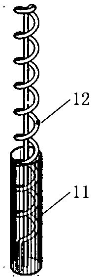
[0039] The dialysis unit 1 includes a dialysis outer tube 11 , a dialysis inner tube 12 and a dialysis membrane. Dialysis outer tube 11 is sleeved on the outer periphery of dialysis inner tube 12. There is a gap between dialysis outer tube 11 and dialysis inner tube 12 to facilitate blood circulation. Dialysis outer tube 11 is hollowed out so that blood enters dialysis outer tube 11 and dialysis tube 12. The space between the inner tubes 12. The dialysis membrane is wrapped on the outer wall of the dialysis inner tube 12, and the dialysis inner tube 12 can be considered to support the dialysis membrane or shape the dialysis membrane. The dialysate flows through the inner dialysis tube 12, and the dialy...

Embodiment 2

[0046] This embodiment provides a chitosan quaternary ammonium salt-polylactic acid composite membrane and a preparation method thereof. The chitosan quaternary ammonium salt-polylactic acid composite membrane is a positively charged hollow fiber membrane, which is used as a dialysis membrane for hemodialysis It has a good application prospect. This chitosan quaternary ammonium salt-polylactic acid composite film is prepared through the following steps:

[0047] Step 1: Take 28g of chitosan quaternary ammonium salt, 109g of polylactic acid, and 32g of polyethylene glycol, and dissolve them in 1L of dimethyl sulfoxide at 50°C to obtain a polylactic acid mixture; add methyl alcohol to the polylactic acid mixture Glycidyl acrylate 0.6g, add 0.001g of azobisisobutyronitrile after 30min of nitrogen gas, raise the temperature to 60°C and carry out free radical polymerization reaction under nitrogen protection for 20h to obtain chitosan mixed with glycidyl methacrylate Quaternary am...


PUM


Abstract

The invention discloses a dialysis tube for hemodialysis and relates to the field of medical equipment. The dialysis tube for hemodialysis provided by the present invention comprises a dialysis part and a connection part, the connection part is connected to the dialysis part; the dialysis part comprises a dialysis outer tube, a dialysis inner tube and a dialysis membrane, and the dialysis outer tube is sleeved on the outer periphery of the dialysis inner tube and There is a gap between the dialysis inner tube and the outer wall of the dialysis inner tube covered by the dialysis membrane; the anticoagulant drug is fixed on the surface of the dialysis membrane; the dialysis inner tube has a U-shaped or V-shaped structure, and the openings are the liquid inlet and outlet respectively. The liquid port; the liquid inlet and the liquid outlet pass through the connection part. The dialysis part of the dialysis device is small in size and can be directly placed in the human artery for hemodialysis without taking blood out of the body and then going through the machine for hemodialysis, so it has no effect on human blood pressure and is more economical, safe and less traumatic than extracorporeal hemodialysis ; It can be indwelling in the blood vessel for multiple uses to continuously perform hemodialysis for the patient.

Description


Claims


Application Information

Patent Timeline
Owner 成都测迪森生物科技有限公司
Why Eureka
Try Eureka