Automatic straightening machine for shaft tube part

A technology for straightening machines and parts, applied in the field of straightening machines, can solve the problems of insufficient straightening accuracy and efficiency, inaccurate maximum deflection surfaces, and unavoidable problems of maximum deflection surface offset, achieving a high degree of automation and improving efficiency. , the effect of improving the accuracy

Active Publication Date: 2018-02-23
YANSHAN UNIV
View PDF6 Cites 21 Cited by
  • Summary
  • Abstract
  • Description
  • Claims
  • Application Information

AI Technical Summary

Problems solved by technology

However, its structure has not been able to realize the automatic positioning function of the maximum deflection surface. It can only rely on artificial positioning of the maximum deflection surface.
The maximum deflection surface selected in this way is not accurate enough, and the offset problem of the maximum deflection surface cannot be avoided during the movement of the shaft, and the alignment accuracy and efficiency are far from enough

Method used


Image

  • Automatic straightening machine for shaft tube part
  • Automatic straightening machine for shaft tube part
  • Automatic straightening machine for shaft tube part

Examples


Embodiment Construction

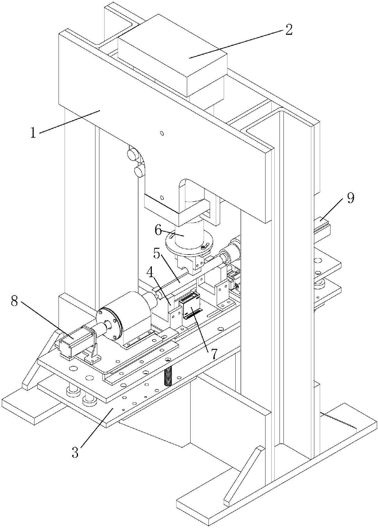
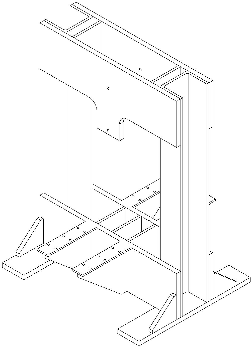
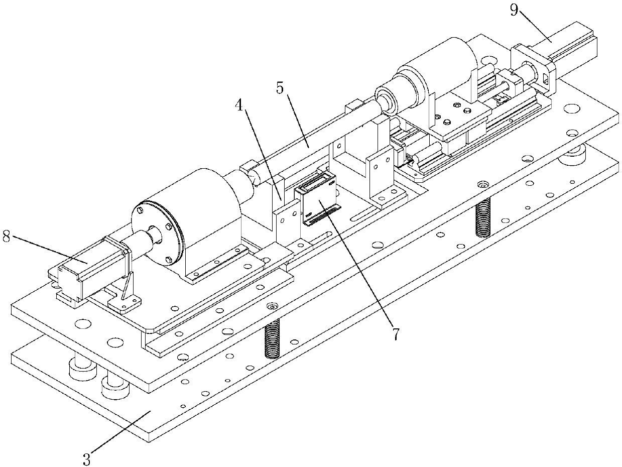
[0023] exist figure 1 , figure 2 and image 3 In the schematic diagram of the automatic straightening machine for shaft and tube parts shown, the frame 1 is a frame structure, the columns on both sides are channel steel, the upper beam is two T-shaped steel plates parallel to each other, and the electric cylinder 2 is connected to the protruding part of the steel plate by bolts Fixed connection, the pressure head 6 is connected with the output shaft of the electric cylinder, the lower beam is two parallel steel plates, each steel plate is equipped with two symmetrical ribs, and the floating workbench 3 is fixed to the ribs of the lower beam by bolts Above; the left rotating device 8 and the right clamping device 9 are respectively set on the left and right sides of the floating workbench, the support seat 4 is set at the central position of the lower fixed plate of the floating workbench, and the alignment member 5 is placed on the support seat , the detection and sensing d...


PUM


Abstract

An automatic straightening machine for a shaft tube part comprises a rack, an electric cylinder, a floating work table, a left rotating device, a right clamping device, a supporting seat and a detecting sensing device. The rack is of a frame structure, the electric cylinder and the floating work table are arranged on an upper transverse beam and a lower transverse beam of the rack correspondingly,and the left rotating device and the right clamping device are arranged on the left side and the right side of the floating work table correspondingly. The supporting seat is arranged in the centralposition of a lower fixing plate of the floating work table, and the detecting sensing device is arranged in the supporting seat. According to the automatic straightening machine for the shaft tube part, in the straightening process, a to-be-straightened piece is clamped at a time so as to achieve the multi-time detecting and straightening functions, and the tedious work procedures that during straightening, after deflection measurement is completed every time, clamping tips need to be loosened, and then the to-be-straightened piece is placed on a V-shaped block to be straightened are avoided;and meanwhile, the problem of maximum deflection face deviation when the clamping tips are loosened to enable the to-be-straightened piece to be placed at the support point is solved, and the efficiency of the straightening machine and the accuracy of straightening are improved.

Description

technical field [0001] The invention belongs to the technical field of machinery, in particular to a straightening machine. Background technique [0002] The straightening machine is a device for straightening the shafts and tubes of the basic parts commonly used in the machinery industry due to thermal deformation and deformation caused by external forces during transportation, so as to meet the installation and operation accuracy requirements of the mechanical system. [0003] However, existing large-scale straightening machines generally perform straightening based on theoretical straightening strokes, and it is often difficult to straighten to within the required precision range at one time, which requires multiple straightening of the bent part to achieve the best precision. However, in most straightening machines, inspection and straightening are carried out separately. First, the deflection of the shaft and tube parts to be straightened is manually detected, and then ...

Claims


Application Information

Patent Timeline
Patent Type & Authority Applications(China)
IPC IPC(8): B21D3/10B21D3/00B21C51/00B21D43/00
CPCB21C51/00B21D3/00B21D3/10B21D43/003
Inventor 马瑞穆振凯翟瑞雪赵军
Owner YANSHAN UNIV
Why Eureka
Try Eureka