
Pneumatic hydraulic damping device of turnover workbench

A technology of damping device and overturning device, which is applied in the direction of manufacturing tools, metal processing equipment, metal processing machinery parts, etc., and can solve problems such as equipment damage, collision, and easy displacement

Pending Publication Date: 2018-02-23
济南天辰智能装备股份有限公司
View PDF8 Cites 3 Cited by
  • Summary
  • Abstract
  • Description
  • Claims
  • Application Information

AI Technical Summary

Problems solved by technology

The three-axis CNC machining center cannot meet its requirements, so a three-sided turning table is required to complete
Due to the large length of the processed profile and the long length of the workbench, in order to prevent deformation of the workbench in the prior art, the cross-section of the workbench is generally enlarged appropriately, and the dead weight of the workbench is about 300kg; both ends of the workbench are equipped with turning devices. The two cylinders are simultaneously pushed and pulled by both ends. Due to the compressibility of the gas in the cylinder and the heavy weight of the workbench, there will be a large impact when the workbench is turned from the positive 90° position to the negative 90° position. When the air pressure is unstable or the solenoid valve controlling the cylinder action is powered off, the angle of the workbench cannot be self-locked, and displacement is likely to occur
For example, when processing at a positive 90° position, if the machine head does not retreat to a safe distance, the angular displacement of the worktable will cause a collision phenomenon and cause great damage to the equipment

Method used


Image

  • Pneumatic hydraulic damping device of turnover workbench
  • Pneumatic hydraulic damping device of turnover workbench
  • Pneumatic hydraulic damping device of turnover workbench

Examples


Embodiment Construction

[0018] The present invention will be further described below through non-limiting examples and in conjunction with the accompanying drawings.

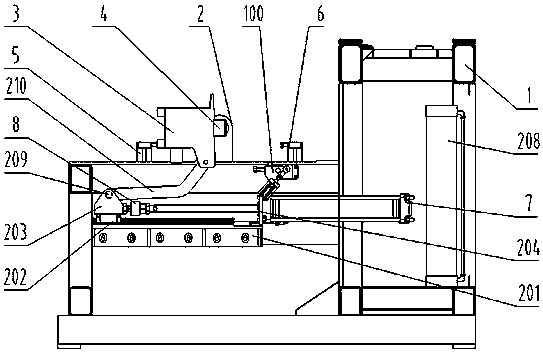
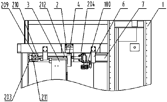
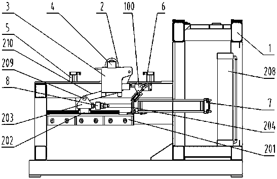
[0019] see figure 1 , a gas-liquid damping device for turning over the workbench, the bed 1 is fixedly connected with a support seat 2, and the workbench 3 is fixedly connected with a rotary support shaft 4, the rotary support shaft is connected with the support seat through a bearing, and the workbench 3 rotates through The support shaft 4 is rotatably connected to the support base 2;

[0020] The bed 1 is fixed with a guide rail seat 201, the linear guide rail pair 202 is fixedly connected to the guide rail seat 201, and the rotary seat 203 is fixedly connected to the slider of the linear guide rail pair 202; The cylinder 7 is fixed on the cylinder fixed seat 204, and the rotary seat 203 is connected with the rod end of the gas-hydraulic cylinder 7 through the floating joint 8,

[0021] A bearing pin A209 is provided on the revolvi...


PUM


Abstract

The invention discloses a pneumatic hydraulic damping device of a turnover workbench. A bed body of the gas-liquid damping device is fixedly connected with a supporting seat, a rotation supporting shaft is fixed to the workbench, and the workbench is rotationally connected to the supporting seat through the rotation supporting shaft. A rotation seat is fixedly connected to a slide block of a linear guide rail pair arranged on the bed body. A pneumatic hydraulic cylinder is arranged on a guide rail seat, the rotation seat is connected with the end of a rod of the pneumatic hydraulic cylinder, one end of a connection rod is hinged to the rotation seat, and the other end of the connection rod is hinged to the workbench. The pneumatic hydraulic cylinder is connected with a pneumatic hydraulicdamping device body which provides hydraulic oil for the pneumatic hydraulic cylinder through a speed control valve and an oil pipe, the pneumatic hydraulic cylinder pushes the rotation seat to move,angle displacement of the workbench is generated through the connection rod, and the workbench is adjusted to stations of +90 degrees, -90 degrees and 0 degree through a limiting device. The hydraulicoil has incompressibility, the flowability of the hydraulic oil is lower than that of gas, thus, the stability of angle displacement of the workbench is ensured, the self-locking performance of the workbench after the workbench is turned over in place is also ensured, impaction is low when the workbench is switched between the stations, and the equipment stability and safety are high.

Description

technical field [0001] The invention relates to a gas-liquid damping device for an overturned workbench, belonging to the technical field of door, window and curtain wall profile processing equipment. Background technique [0002] In the field of door, window and curtain wall processing, the same profile needs to be processed on three surfaces, such as milling for the installation holes of door and window handles, and milling for the installation holes of curtain wall keels. The three surfaces have positional requirements. The three-axis CNC machining center cannot meet its requirements, so a worktable with three-sided flip is required to complete it. Due to the large length of the processed profile and the long length of the workbench, in order to prevent deformation of the workbench in the prior art, the cross-section of the workbench is generally enlarged appropriately, and the dead weight of the workbench is about 300kg; both ends of the workbench are equipped with turni...

Claims


Application Information

Patent Timeline
IPC IPC(8): B23Q1/26B23Q1/64
CPCB23Q1/26B23Q1/64Y02P70/10
Inventor 亓爱林王丛丛苗青晓
Owner 济南天辰智能装备股份有限公司
Learn More