
Central hole positioning fixture for drilling lug hole of spline shaft fork

A spline shaft fork, positioning fixture technology, applied in positioning devices, clamping, manufacturing tools, etc., can solve the problems of poor blank surface consistency, large center height dimensional changes, machining errors, etc., to avoid machining errors and ensure the position. degree of effect

Inactive Publication Date: 2018-02-23
XUCHANG YUANDONG DRIVE SHAFT
View PDF7 Cites 6 Cited by
  • Summary
  • Abstract
  • Description
  • Claims
  • Application Information

AI Technical Summary

Problems solved by technology

At present, in the processing of spline shaft fork drilling ear holes, the positioning method is to use the arc blank surface of the spline shaft fork to locate. The specific operation is to put the spline shaft fork into the V-shaped block in the equipment to be processed, and use the pressing device The shaft fork and the V-shaped groove of the V-shaped block are pressed together to drill the ear holes, and the previous processing is to use the processed center hole for positioning, and there is a datum conversion, which is easy to cause processing errors; during the processing, due to the shaft The fork is affected by forging and heat treatment, and the consistency of the blank surface is poor, which leads to the unstable position of the ear hole, which will affect the subsequent processing. The subsequent milling spline processing is to use the center hole and ear hole positioning for milling. Without participating in the positioning, the position of the ear hole and the center hole cannot be guaranteed, so after milling, the phase angle of the spline relative to the center axis of the ear hole cannot guarantee its stability, which affects the customer's requirements for the product phase angle; in addition, the center height of the ear hole has a certain According to the requirement, the consistency of blank surface positioning is poor, and the center height dimension changes greatly, resulting in insufficient allowance for subsequent ear hole boring, resulting in waste products

Method used


Image

  • Central hole positioning fixture for drilling lug hole of spline shaft fork
  • Central hole positioning fixture for drilling lug hole of spline shaft fork

Examples


Embodiment Construction

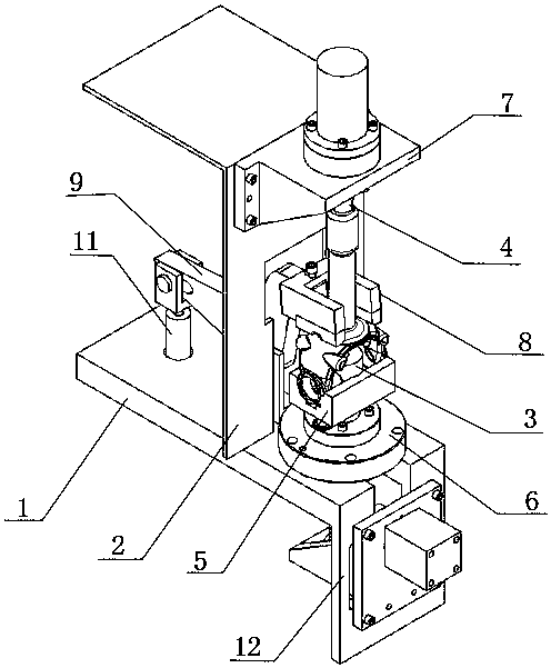
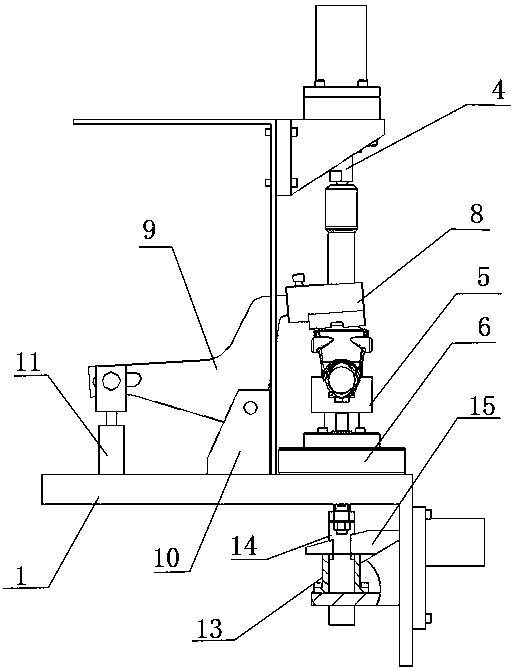
[0013] As shown in the figure: a center hole positioning fixture for spline shaft fork drilling ear holes, including base 1, clamp body support plate 2, fixed top 3, movable top 4, V-shaped block 5, pressing device and V-shaped The block adjustment device 12, the base 1 is horizontally installed on the processing machine tool, the clamp body support plate 2 is vertically arranged with the base 1, the clamp body support plate 2 is fixed with a movable top seat 7 by bolts, and a hydraulic cylinder and a hydraulic cylinder are installed on the movable top seat 7. The movable center 4 is driven and controlled by a hydraulic cylinder; the base is fixed with a fixed center seat 6 by bolts, the fixed center 3 is mounted on the fixed center seat 6, and the movable center 4 and the fixed center 3 are coaxially arranged and the centers are opposite to each other. ; The V-shaped block 5 is movably installed on the shaft body of the fixed top 3, the length direction of the V-shaped groove ...


PUM


Abstract

The invention relates to the technical field of spline shaft fork machining fixtures, in particular to a central hole positioning fixture for drilling a lug hole of a spline shaft fork. The central hole positioning fixture comprises a pedestal, a fixed centre, a movable centre, a V-shaped block, a pressing device and a V-shaped block adjustment device, wherein the fixed centre and the movable centre are coaxial, and the centre directions are opposite to clamp a workpiece in a central hole positioning manner; the movable centre is driven by a hydraulic cylinder; the pressing device is arrangedon one side, which is back onto the fixed centre, of a fixture body supporting plate; a hydraulic device adjusts a connection plate to control a pressing block to cooperate with the V-shaped block tofix the workpiece, so that the machining stability is guaranteed; the V-shaped block adjustment device is arranged below the pedestal; and an adjustment rod is adjusted through a cylinder to realize up-and-down movement of the V-shaped block. The central hole positioning fixture for drilling the lug hole of the spline shaft fork guarantees the consistency of all working procedure positioning references during machining; the position stability of the lug hole relative to a central hole is greatly improved; and furthermore, in a subsequent spline milling working procedure, a phase angle of a spline relative to the lug hole is more precise, and the quality of a product is improved.

Description

technical field [0001] The invention relates to the technical field of a spline shaft yoke processing positioning fixture, in particular to a center hole positioning jig used for spline shaft yoke drilling ear holes. Background technique [0002] With the continuous globalization of the market economy, my country's machinery manufacturing industry participates in the competition of global industries. The rapid development and changes of the market require domestic enterprises to have rapid and strong adaptability and the ability to respond to the economic market. With the continuous development of social economy, the continuous increase of labor costs, and the continuous progress of scientific and technological achievements, the role of mechanical automation will become more and more important. It is imperative to promote the production automation of enterprises. Therefore, in the automatic production line of robot intelligent manufacturing, and The tooling and fixture desig...

Claims


Application Information

Patent Timeline
IPC IPC(8): B23Q3/08
CPCB23Q3/082
Inventor 刘金檑付浩锋赵贺周建喜马喜岭陈云升李建勋潘天林韩利尚国生张鹏超张俊华曹善江吴鹏何晓敏柴二帅姚晋业梁东杰李磊顾鲜美雷务然
Owner XUCHANG YUANDONG DRIVE SHAFT
Features
  • Generate Ideas
  • Intellectual Property
  • Life Sciences
  • Materials
  • Tech Scout
  • Unparalleled Data Quality
  • Higher Quality Content
  • 60% Fewer Hallucinations
Learn More