
Self-adaption inner cylinder clamping manipulator

A manipulator, self-adaptive technology, applied in the field of manipulators, can solve the problems of increased control cost, large generation, unstable clamping, etc., to achieve stable control, small torque effect, and meet the clamping requirements.

Inactive Publication Date: 2018-02-23
WENZHOU POLYTECHNIC
View PDF8 Cites 9 Cited by
  • Summary
  • Abstract
  • Description
  • Claims
  • Application Information

AI Technical Summary

Problems solved by technology

[0004] The cylindrical clamping manipulator can meet the clamping requirements of thin-walled parts, but because it drives the radial movement of the clamping head through the eccentric distance between the connecting rod and the control disc, during the rotation of the control disc, the Circular motion drives the connecting rod to swing, which is then converted into linear motion of the clamping head. If the speed of the control panel is constant, the speed of the linear motion of the clamping head will be unstable, which will lead to instantaneous friction between the clamping head and the thin-walled parts. The contact pressure and clamping force cannot be precisely controlled; if the clamping head is to be controlled to maintain a constant rate of movement, the requirement for controlling the rotation rate of the control disc is too high, which increases the control cost
[0005] In addition, during the clamping process of the cylinder clamping manipulator, although theoretically speaking, it can realize the clamping of thin-walled parts of different sizes, but at other clamping positions other than the dead point, due to the control panel and the connecting rod Being subjected to the reaction force of the clamping force, the reaction force will generate a large torque relative to the axis of the control disc, causing the control disc to be unstable, which in turn leads to unstable clamping; therefore, in actual use, the cylinder clamps the manipulator There is only one stable clamping point at the dead point (the position point when the connecting rod and the guide rail are both located in the radial direction), that is, the cylinder clamping manipulator can only meet the clamping of cylinder parts of a specific size during actual use. hold

Method used


Image

  • Self-adaption inner cylinder clamping manipulator
  • Self-adaption inner cylinder clamping manipulator
  • Self-adaption inner cylinder clamping manipulator

Examples


Embodiment Construction

[0032] The present invention will be further described below in conjunction with the accompanying drawings and specific embodiments, so that those skilled in the art can better understand the present invention and implement it, but the examples given are not intended to limit the present invention.

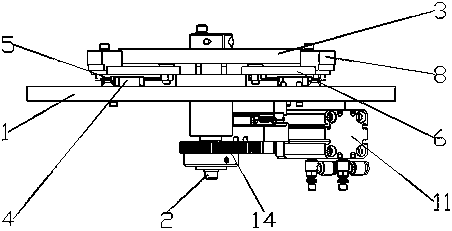
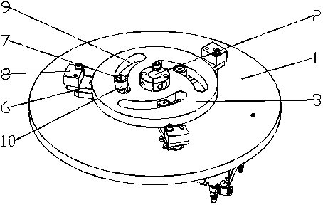
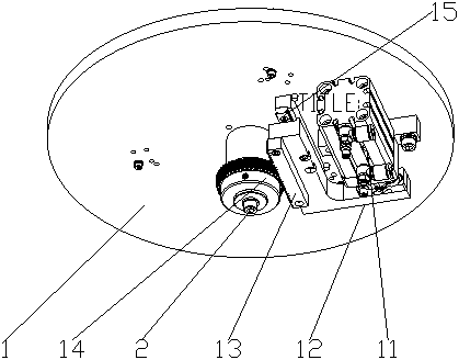
[0033] Such as figure 1 Shown is a schematic structural view of an embodiment of the self-adaptive inner cylinder clamping manipulator of the present invention. The self-adaptive inner cylinder clamping manipulator of this embodiment comprises a chassis 1, a rotating shaft 2 cooperating with its rotation is provided at the center of the bottom plate 1, and a control panel 3, which rotates synchronously with it and is located above the chassis 1, is set on the rotating shaft 2. Between 3 and the chassis 1, at least three clamping units are evenly distributed in a ring. In this embodiment, three clamping units are evenly distributed in a ring. Of course, the number of clamping unit...


PUM


Abstract

The invention discloses a self-adaptive inner cylinder clamping manipulator, which includes a chassis, a rotating shaft cooperating with the rotating shaft is arranged in the center of the bottom plate, a control disk is set on the rotating shaft, and at least three clamps are evenly arranged in a ring between the control disk and the chassis. holding unit; the clamping unit includes a radial slide seat fixedly installed on the chassis, a slide rail is provided on the radial slide seat for sliding cooperation with it, a connecting block is fixedly installed on the slide rail, and one end of the connecting block radially inward There is a sliding shaft, and the radially outward end of the connecting block is provided with a clamping head. The axis of the sliding shaft is parallel to the axis of the rotating shaft. The control panel is provided with a stroke groove corresponding to the sliding shaft, and the sliding shaft extends into the stroke groove. and cooperate with the stroke groove; the distance y between the centerline of the stroke groove and the axis of the rotating shaft satisfies: y=aθ+b, θ is the radial direction of any point on the centerline of the stroke groove relative to the axis of the rotating shaft and the distance between the stroke groove The angle between the point where the centerline is closest to the shaft axis and the radial direction of the shaft axis.

Description

technical field [0001] The invention belongs to the technical field of manipulators, in particular to an adaptive inner cylinder clamping manipulator. Background technique [0002] Manipulator is a high-tech automatic production equipment developed in recent decades, which can accurately grasp objects of specific shapes. However, for thin-walled cylindrical workpieces, existing manipulators often cannot meet the grasping requirements of thin-walled cylindrical workpieces because they are prone to deformation. [0003] The Chinese patent with the publication number CN107175676A discloses a cylinder clamping manipulator, comprising: a guide rail mounting seat; an actuator, which includes a rotating cylinder, a cylinder rotating shaft and a control panel, and the rotating cylinder is controlled by the rotating shaft of the cylinder. The panel key connection, the control panel is located in the middle of the bottom of the guide rail mounting seat, and the rotating cylinder is l...

Claims


Application Information

Patent Timeline
IPC IPC(8): B25J15/02B25J15/08B25J15/12
CPCB25J15/0253B25J15/08B25J15/12
Inventor 黄其祥
Owner WENZHOU POLYTECHNIC
Learn More