Separation settling tank

A separation tank and sedimentation tank technology, applied in the field of separation and sedimentation tanks, can solve the problems of low production efficiency of plastic products, affecting the separation of plastic mixtures, and difficulty in automatic separation and recovery of floating and sinking materials, so as to improve recovery efficiency, Guaranteed effect

Pending Publication Date: 2018-02-23
GENOX RECYCLING TECH
0 Cites 14 Cited by

AI-Extracted Technical Summary

Problems solved by technology

[0004] (1) Most of the separation and sedimentation tanks are difficult to automatically separate and recycle floating materials and sinking materials, resulting in low production efficiency of plastic product recycling;
[0005] (2) The concentration of the separatio...

Method used

As a preferred embodiment of the cleaning roller 132, the cleaning plate 1323 includes a panel 1324 and a side panel 1325 that is connected to the two ends of the panel 1324 respectively. direction bend. In this way, the second drive shaft 1322 drives the second cylinder body 1321 to rotate, and the cleaning plate 1323 rotates accordingly; the cleaning plate 1323 stirs the plastic mixture during the movement, so that the plastic mixture fully enters the separation tank main body 10, and fully contacts and soaks with the separation liquid. , to speed up the separation of floating material and sinking material; and the panel 1324 of the cleaning plate 1323 pushes the plastic mixture into the separation liquid for cleaning, and the side plate 1325 can prevent the floating material in the plastic mixture from spreading around, and the floating material moves forward under the push of the panel 1324 The movement is finally collected, and the sinking material sinks to the bottom of the main body 10 of the separation tank to be collected.
During the use of the present invention, the plastic mixture is transported into the separation tank main body 10 through the feed port 11 from the outside of the separation sedimentation tank by the production line, and the plastic mixture is dispersed through the material distribution assembly 13 from the separation tank main body 10, The plastic mixture is evenly dispersed in the main body 10 of the separation tank...

Abstract

The invention discloses a separation settling tank and belongs to the technical field of separation equipment. The separation settling tank comprises a separation tank body, a collection device arranged on the lower portion of the separation tank body and a support used for supporting the separation tank body and the collection device. The collection device communicates with the interior of the separation tank body. One end of the separation tank body is provided with a feed port. The other end of the separation tank body is provided with a storage cavity. The separation tank body is internally provided with a material separation assembly used for separating a plastic mixture and a material shifting assembly used for shifting floating materials. The material separation assembly gets closeto the feed port. The material shifting assembly gets close to the storage cavity. The separation tank body is further provided with a concentration regulation mechanism used for controlling the concentration of a separating medium in the separation tank body. The separation settling tank can automatically separate and recover the floating materials and settling materials, automatically regulationthe concentration of the separating medium and improve the recovery efficiency and quality of plastic products.

Application Domain

Technology Topic

Material SeparationCell separation +2

Image

  • Separation settling tank
  • Separation settling tank
  • Separation settling tank

Examples

  • Experimental program(1)

Example Embodiment

[0029] In the following, the present invention will be further described in conjunction with the drawings and specific implementations. It should be noted that, provided that there is no conflict, the following embodiments or technical features can be combined to form new embodiments. .
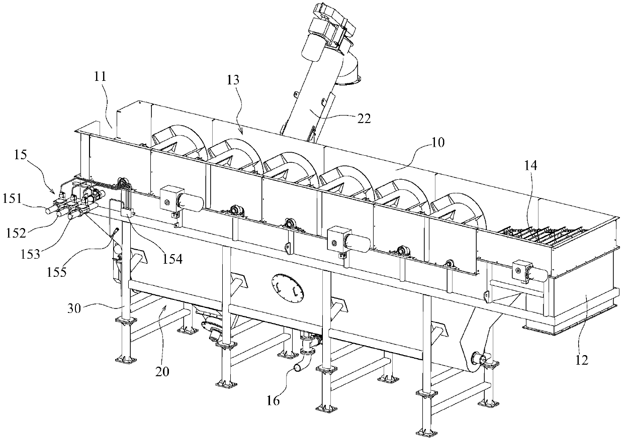
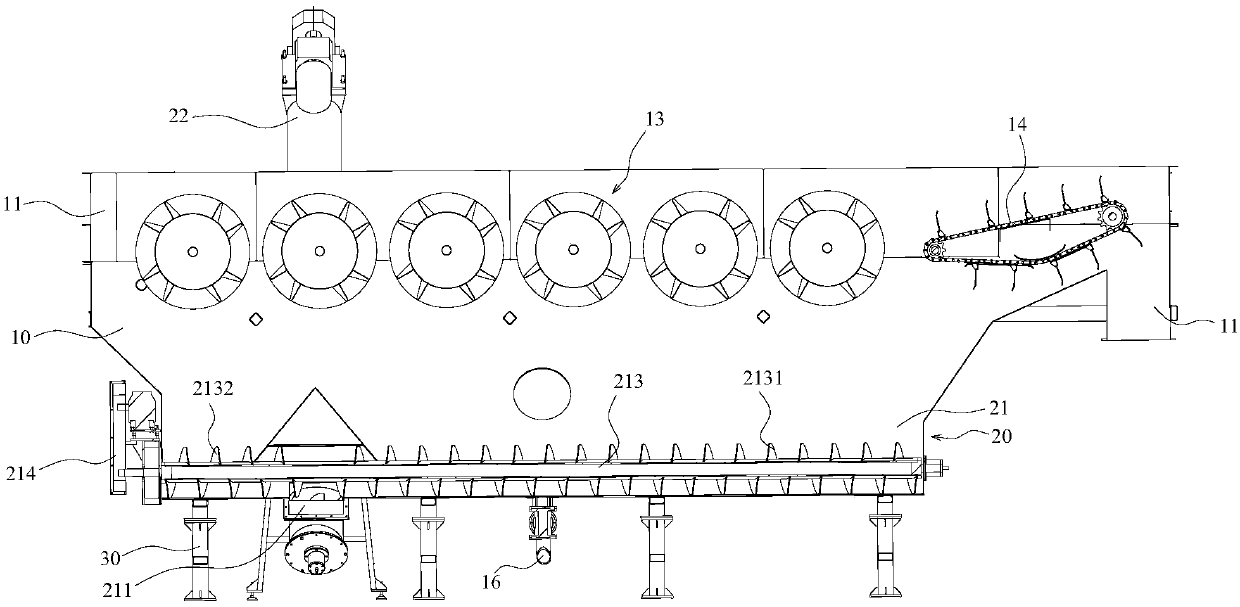
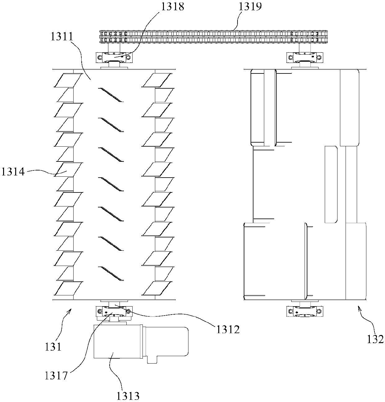
[0030] Such as Figure 1-3 As shown, in order to realize automatic separation and recycling of plastic products, the present invention provides a separation sedimentation tank. The separation sedimentation tank includes a separation tank main body 10, a collection device 20 arranged at the lower part of the separation tank main body 10, and a supporting separation tank. The main body 10 and the support 30 of the collecting device 20, the collecting device 20 communicates with the inside of the separation tank main body 10, and is used to collect the sediment after the separation of the plastic mixture in the separation tank main body 10; one end of the separation tank main body 10 is provided with a feed port 11 , Used to put the plastic mixture that needs to be separated and recycled into the separation tank body 10, the other end of the separation tank body 10 is provided with a storage cavity 12 for collecting the floating material after the separation of the plastic mixture; the separation tank body 10 is equipped with It is used for separating the plastic mixture 13 and the shifting component 14 for shifting the floating material. The distributing component 13 is close to the feed port 11, and the shifting component 14 is close to the storage cavity 12; the separation tank body 10 is also provided for control The concentration adjustment mechanism 15 for the concentration of the separation liquid inside the separation tank main body 10 is used for real-time monitoring of the separation liquid in the separation tank main body 10 and adjusts according to the preset concentration of the separation liquid.
[0031] During the use of the present invention, the plastic mixture is transported from the outside of the separation sedimentation tank through the feed port 11 into the separation tank body 10 through the production line, and the plastic mixture is dispersed from the separation tank body 10 through the distributing assembly 13 to make the plastic mixture Evenly dispersed in the main body of the separation tank 10 and can be immersed in the separation liquid, and then the plastic mixture is drifting towards one end of the storage cavity 12, the distributing component 13 separates the plastic mixture, and separates the floating material in the plastic mixture and The sediment is separated, the sediment sinks into the bottom of the separation tank main body 10 and is collected and recovered by the collection device 20, while the float continues to drift forward and is finally transferred to the storage cavity 12 by the shift component 14 for collection. In this process, because the concentration of the separation liquid will change with the process, it is necessary to adjust the concentration of the separation liquid. The previous separation sedimentation tank needs to discharge all the separation liquid in the separation tank every time it is used. And re-inject the separation liquid with the required concentration, which is expensive and also affects the recovery efficiency. The present invention uses the concentration adjustment mechanism 15 to detect and supplement the separation liquid concentration in the separation tank body 10 in real time, so that the separation liquid even after a long time The concentration of the separation process can also be guaranteed, and finally the automatic separation and collection of plastic waste for a long time can be realized.
[0032] Such as Figure 4-7 As shown, the distributing assembly 13 includes a distributing roller 131 for uniformly dispersing the plastic mixture and a plurality of cleaning rollers 132 for separating the plastic mixture; the distributing roller 131 is close to the feed port 11, and the plurality of cleaning rollers The barrel 132 is located between the distribution roller 131 and the material shifting assembly 14.
[0033] Further, the distribution roller 131 includes a first cylinder 1311, a first drive shaft 1312, and a first drive motor 1313 connected to the first drive shaft 1312; the first drive shaft 1312 is fixedly connected to the first cylinder 1311, The outer peripheral surface of the first cylinder body 1311 is uniformly fixed with a plurality of material dividing pieces groups; each material dividing piece group includes a plurality of material dividing pieces 1314, and the dividing pieces 1314 of any adjacent material dividing piece group are in the first cylinder body. 1311 staggered divisions in the direction of the central axis. In this way, when the plastic mixture is put into the main body 10 of the separation tank, the material divider 1314 scatters the plastic mixture, avoiding the appearance of large lumps of the plastic mixture, thereby helping to separate the floating material and sinking material in the plastic mixture.
[0034] As a preferred embodiment of the material dividing roller 131, the material dividing sheet 1314 includes a main plate 1315 and two dividing plates 1316 connected to both ends of the main plate 1315; the main plate 1315 and the central axis of the first cylinder 1311 form an angle, and the angle is -90 °~90°; in this way, the plastic mixture is moved along the main board 1315 through the dividing plate 1316, so that the plastic mixture is well dispersed.
[0035] The first drive shaft 1312 has a first installation end 1317 and a second installation end 1318. Both the first installation end 1317 and the second installation end 1318 extend from the inside of the first cylinder 1311 to the outside of the first cylinder 1311, and the first installation The end 1317 is fixedly connected to the output shaft of the first drive motor 1313, the outer wall of the second mounting end 1318 is fixedly sleeved with a sprocket, and a first drive chain 1319 is provided on the sprocket.
[0036] The cleaning roller 132 includes a second cylinder 1321 and a second drive shaft 1322; the second drive shaft 1322 is fixed through the second cylinder 1321, and a plurality of cleaning plate groups are fixed on the outer peripheral surface of the second cylinder 1321; A cleaning plate group includes a plurality of cleaning plates 1323 that evenly surround the outer peripheral surface of the second cylinder 1321; any two adjacent cleaning plates 1323 are staggered, so that the cleaning plates 1323 push the plastic mixture into the separation liquid for cleaning, thereby causing floating The material and the sinking material are separated; in addition, the cleaning plate 1323 pushes the floating material forward to move the floating material to the vicinity of the shifting assembly 14 to facilitate the shifting assembly 14 to grab the floating material; the first drive chain 1319 is installed on the sprocket and The distribution roller 131 is adjacent to the second drive shaft 1322 of the cleaning roller 132. Due to the provision of the first transmission chain 1319, when the dividing roller 131 rotates, it drives the cleaning roller 132 adjacent to the dividing roller 131 to rotate together, so that the dividing roller 131 and the cleaning roller can be driven by the first drive motor 1313. 132 rotates together at the same speed.
[0037] As a preferred embodiment of the cleaning roller 132, the cleaning plate 1323 includes a panel 1324 and side panels 1325 respectively connected to both ends of the panel 1324. The upper part of the panel 1324 is provided with a bending structure, and the bending structure is bent in a direction close to the side panel 1325 . In this way, the second drive shaft 1322 drives the second cylinder 1321 to rotate, and the cleaning plate 1323 rotates accordingly; the cleaning plate 1323 toggles the plastic mixture during the movement, so that the plastic mixture fully enters the separation tank body 10, and fully contacts and soaks with the separation liquid Speed ​​up the separation of floating and sinking materials; while the panel 1324 of the cleaning plate 1323 pushes the plastic mixture into the separation liquid for cleaning. The side plate 1325 can prevent the floating material in the plastic mixture from spreading, and the floating material is pushed forward by the panel 1324. The movement is finally collected, and the sediment sinks into the bottom of the separation tank body 10 to be collected.
[0038] Such as Figure 7 As shown, the material shifting assembly 14 includes a driving shaft 141, a driven shaft 142, a second driving motor 143, and two second transmission chains 144; the second driving motor 143 is connected to the driving shaft 141, and the second transmission chain 144 is installed on the driving shaft On 141 and the driven shaft 142, and between the two second transmission chains 144, a plurality of shifting members 145 are fixed. The second driving motor 143 drives the driving shaft 141 to rotate, the driving shaft 141 drives the driven shaft 142 to rotate through the second transmission chain 144, and the material shifting member 145 moves along with the second transmission chain 144; the material shifting member 145 is in motion, The floating material is hung on the shifting member 145, thereby automatically removing the floating material from the separation liquid and transporting the floating material to the storage cavity 12.
[0039] In order to better grasp the floating material, the material shifting member 145 includes a mounting rod 1451 and a plurality of scraping claws 1452. The mounting rod 1451 is fixedly connected between the two second transmission chains 144, and the scraping claws 1452 are fixed to the mounting rod 1451. There are a plurality of scraping claws 1452 arranged at equal intervals, and the upper part of the scraping claws 1452 is provided with a bending structure.
[0040] The collection device 20 includes a conveying cavity 21 and a screw conveyor 22. The conveying cavity 21 is in communication with the inside of the separation tank body 10, a discharge port 211 is provided at the lower part of the conveying cavity 21, and the conveying cavity 21 communicates with the screw conveyor 22 through the discharge port 211; The conveying cavity 21 is provided with a screw conveying shaft 213. The screw conveying shaft 213 is used to convey the sinking material in the conveying cavity 21 to the discharge port 211 at the bottom of the conveying cavity 21. The third drive motor 214.
[0041] The screw conveying shaft 213 includes a shaft body and a first spiral structure 2131 and a second spiral structure 2132 fixed on the shaft body; the first spiral structure 2131 and the second spiral structure 2132 are respectively located on both sides of the discharge port 211; The spiral direction of the spiral structure 2131 is opposite to the spiral direction of the second spiral structure 2132. When the screw conveying shaft 213 is driven to rotate, the spiral directions of the first spiral structure 2131 and the second spiral structure 2132 are opposite, and the sinking materials located on both sides of the discharge port 211 are transported to the discharge port 211, effectively avoiding sinking Blocked inside the delivery chamber 21.
[0042] The concentration adjustment mechanism 15 includes a plurality of water inlet pipes, which are respectively connected with different concentrations of separated liquid and clean water; the multiple water inlet pipes are respectively provided with solenoid valves 154; the separation tank body 10 is also provided with a device for detecting the concentration of the separated liquid in the tank Detection sensor 155.
[0043] Preferably, there are three water inlet pipes. The three water inlet pipes are respectively used for the clear water pipe 151 for transporting clean water, the high-concentration pipe 152 for transporting the separation liquid with a concentration higher than the preset value, and the preset concentration for transporting the separation liquid. Tube 153. Under normal conditions, the preset tube 153 is opened. When the detection sensor 155 detects that the concentration of the separation liquid in the separation tank body 10 is lower than the preset value, the preset tube 153 is closed and the high-concentration tube 152 is opened as the separation tank The main body 10 is injected with a separation liquid whose concentration is higher than a preset value to increase the overall concentration of the separation liquid. When the concentration of the separation liquid reaches the preset requirement, the high-concentration tube 152 is closed and reset again, and the preset tube 153 is opened; 155 When it is detected that the concentration of the separation liquid in the separation tank main body 10 is higher than the preset value, the default pipe 153 is closed, and the clear water pipe 151 is opened to inject clean water into the separation tank main body 10 to reduce the overall concentration of the separation liquid. After the preset requirements are met, the clean water pipe 151 is closed and reset again, and the preset pipe 153 is opened to achieve the effect of automatically adjusting the concentration of the separated liquid.
[0044] In order to facilitate the replacement of the separation liquid and cleaning of the separation tank main body 10, the bottom of the separation tank main body 10 is also provided with a drain port 16 communicating with the inside of the separation tank main body 10.
[0045] The foregoing embodiments are only preferred embodiments of the present invention, and cannot be used to limit the scope of protection of the present invention. Any insubstantial changes and substitutions made by those skilled in the art on the basis of the present invention belong to the present invention. The scope of protection required.

PUM

no PUM

Description & Claims & Application Information

We can also present the details of the Description, Claims and Application information to help users get a comprehensive understanding of the technical details of the patent, such as background art, summary of invention, brief description of drawings, description of embodiments, and other original content. On the other hand, users can also determine the specific scope of protection of the technology through the list of claims; as well as understand the changes in the life cycle of the technology with the presentation of the patent timeline. Login to view more.

Similar technology patents

Extensible regenerative brake control system

InactiveCN107499143AAvoid vehicle instabilityImprove recycling efficiencyElectrodynamic brake systemsFour-wheel driveEngineering
Owner:EASTONE AUTOMOTIVE TECH

Cut tobacco recycling device for waste cigarettes

ActiveCN109330019AImprove recycling efficiencyCollege cut effectCigarette manufactureVortex flow apparatusScrapFine paper
Owner:郑州格兰高环境工程有限公司

Classification and recommendation of technical efficacy words

  • Improve recycling efficiency
  • Guaranteed effect
Why Eureka
Try Eureka