
Military multifunctional textile fabric decontaminating device

A textile fabric and multi-functional technology, applied in the direction of processing textile material equipment configuration, processing textile material drums, processing textile material carriers, etc., can solve the problems of manual movement, inconvenient decontamination, and low cloth efficiency, etc., to improve mechanical The effect of automation ability, improvement of water recycling efficiency, and improvement of cleanliness

Inactive Publication Date: 2018-02-23
浙江盛伦科技有限公司
View PDF7 Cites 2 Cited by
  • Summary
  • Abstract
  • Description
  • Claims
  • Application Information

AI Technical Summary

Problems solved by technology

[0003] Chinese patent publication application number is: CN205803829U discloses a kind of textile fabric decontamination device, and this device is fixed with straight tube on table body, and the upper part of this straight tube has inclined slit and is covered with supporting net cloth on this inclined slit to form inclination. On the support surface, there is also a clamp for fastening the support mesh on the straight cylinder, and a water tank is placed under the straight cylinder; there is also a high-pressure water gun for spraying high-pressure water to the stains of the textile fabric covering the inclined support surface. The whole decontamination process does not require any detergent, and the consumption of water is less, and the consumed water can be recycled, no pollution, no special waste water treatment equipment is needed, the disadvantage of this device is that it needs to manually move the cloth and high pressure Water gun, resulting in inefficient decontamination of fabrics, not easy to decontaminate

Method used


Image

  • Military multifunctional textile fabric decontaminating device
  • Military multifunctional textile fabric decontaminating device
  • Military multifunctional textile fabric decontaminating device

Examples


Embodiment Construction

[0023] In describing the present invention, it should be understood that the terms "center", "longitudinal", "transverse", "length", "width", "thickness", "upper", "lower", "front", " Orientation indicated by rear, left, right, vertical, horizontal, top, bottom, inside, outside, clockwise, counterclockwise, etc. The positional relationship is based on the orientation or positional relationship shown in the drawings, and is only for the convenience of describing the present invention and simplifying the description, rather than indicating or implying that the referred device or element must have a specific orientation, be constructed and operated in a specific orientation, Therefore, it should not be construed as limiting the invention.

[0024] In addition, the terms "first" and "second" are used for descriptive purposes only, and cannot be interpreted as indicating or implying relative importance or implicitly specifying the quantity of indicated technical features. Thus, a ...


PUM


Abstract

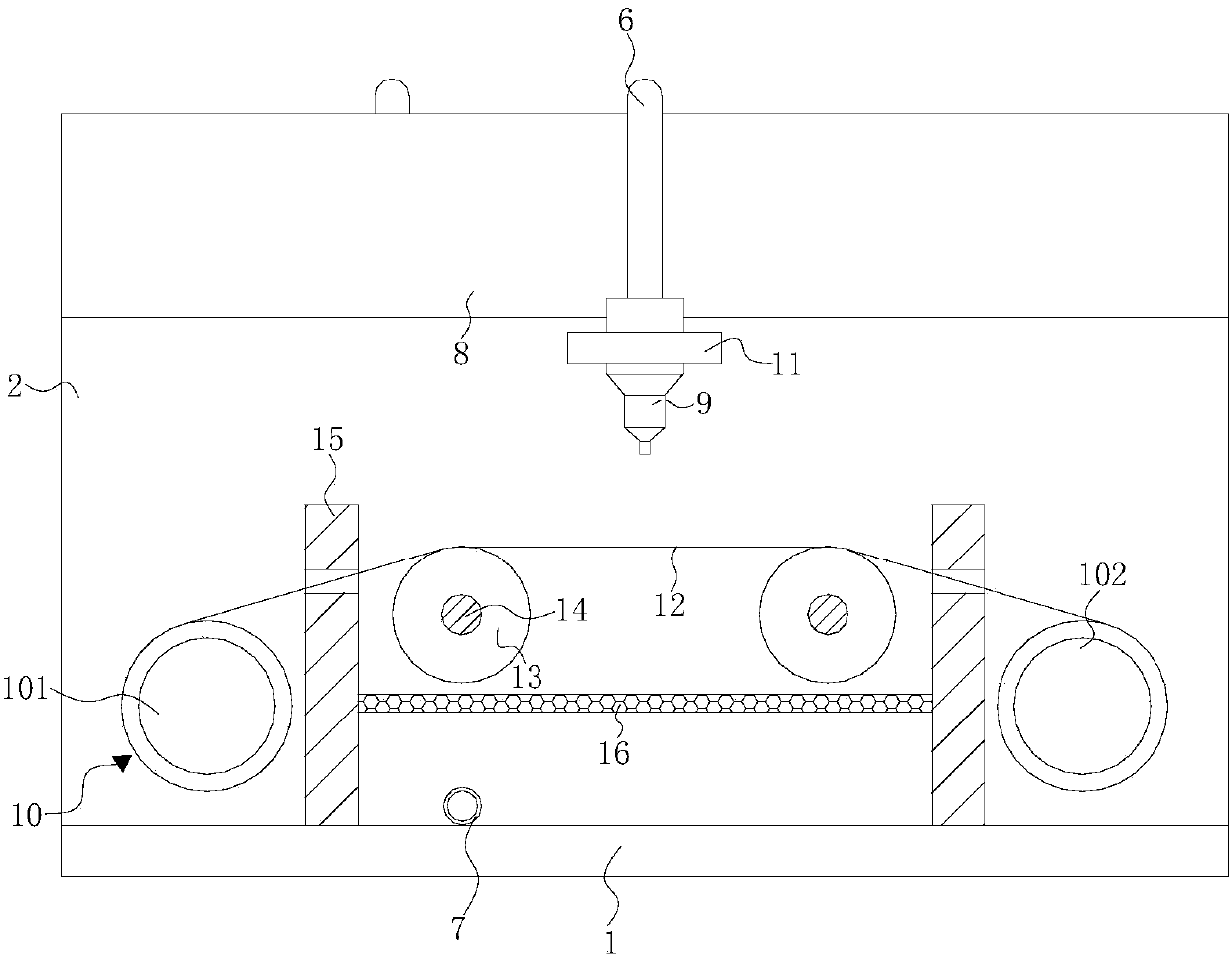
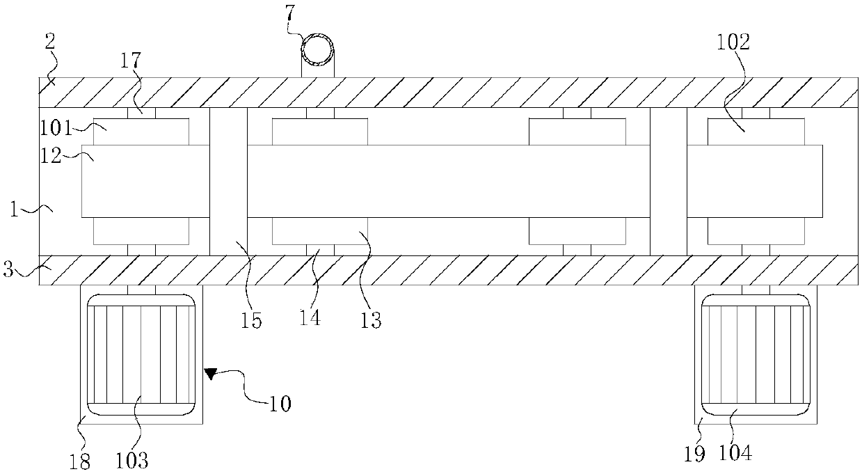
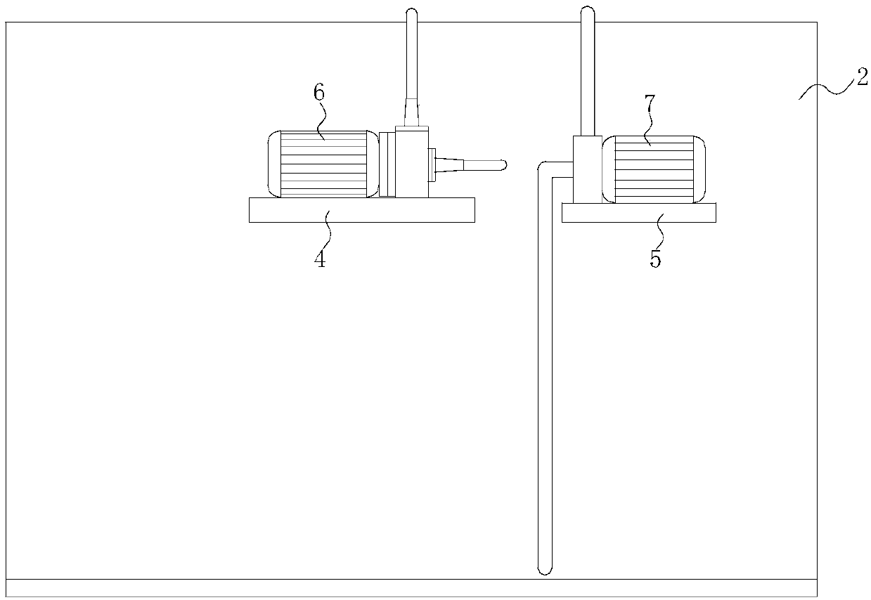
The invention discloses a military multifunctional textile fabric decontaminating device. The military multifunctional textile fabric decontaminating device comprises a bottom plate, wherein the top of the bottom plate is fixedly connected with a first vertical plate and a second vertical plate; the first vertical plate is positioned on the back surface of the second vertical plate; the back surface of the first vertical plate is fixedly connected with a first placement plate and a second placement plate; the first placement plate is positioned on the right side of the second placement plate;the top of the first placement plate and the top of the second placement plate are separately fixedly connected with a first water pump and a second water pump; the top of the front surface of the first vertical plate is fixedly connected with a water tank and a high-pressure water gun; the high-pressure water gun is positioned at the bottom of the water tank; a water outlet tube of the first water pump communicates with the high-pressure water gun; and a water inlet tube of the first water pump communicates with the water tank. By arrangement of the first water pump, the water tank, the high-pressure water gun and a fabric reeling device of the military multifunctional textile fabric decontaminating device, requirements of artificial operation can be reduced, mechanical automation abilityis improved, fabrics and the water gun do not need to move manually, and the fabric decontaminating efficiency can be improved.

Description

technical field [0001] The invention relates to the technical field of fabric processing equipment, in particular to a military multifunctional textile fabric decontamination device. Background technique [0002] Fabric is the material used to make clothing. As one of the three elements of clothing, fabric can not only interpret the style and characteristics of clothing, but also directly affect the color and shape of clothing. [0003] Chinese patent publication application number is: CN205803829U discloses a kind of textile fabric decontamination device, and this device is fixed with straight tube on table body, and the upper part of this straight tube has inclined cut and is covered with supporting net cloth on this inclined cut to form inclined. On the support surface, there is also a clamp for fastening the support mesh on the straight cylinder, and a water tank is placed under the straight cylinder; there is also a high-pressure water gun for spraying high-pressure wat...

Claims


Application Information

Patent Timeline
Patent Type & Authority Applications(China)
IPC IPC(8): D06B1/02D06B23/04D06B23/20D06B23/02
Inventor 杨文龙
Owner 浙江盛伦科技有限公司
Learn More